Summary of PIC16F88 DIGITAL VOLTMETER CIRCUIT
This article describes a PIC16F88-based digital voltmeter project using C firmware. It measures up to 20V with ~10 mV resolution via the PIC's ADC, displays readings on five-digit 7-segment LEDs driven by 74LS47/74HC47 BCD-to-seven-segment drivers and 74HC238 digit drivers, and uses reference voltage calibration to improve accuracy. Source schematic, C source, and HEX files are provided for download.
Parts used in the PIC16F88 VOLTMETER PROJECT:
- PIC16F88 microcontroller
- 7-segment LED displays (five-digit)
- 74LS47 or 74HC47 BCD-to-7-segment driver IC(s)
- 74HC238 3-to-8 line decoder/digit driver
- Resistors for segment current limiting
- Reference voltage source (for ADC calibration)
- Analog input protection components (e.g., series resistor, clamp diodes)
- Power supply (regulated for the circuit)
- Miscellaneous wiring, PCB or breadboard, connectors
Voltmeter circuit PIC16F88 microcontroller C language prepared by the program based on the indicators used for the 7-segment LED display with integrated TTL 74ls47 74hc238 and are driven. pic16F88 of AD was made using a digital voltmeter conversion. The… Electronics Projects, PIC16F88 Digital Voltmeter Circuit “microchip projects, microcontroller projects, pic16f88 projects,
Voltmeter circuit PIC16F88 microcontroller C language prepared by the program based on the indicators used for the 7-segment LED display with integrated TTL 74ls47 74hc238 and are driven. pic16F88 of AD was made using a digital voltmeter conversion. The goal is practical resolution of about 10mV maximum voltmeter that can measure up to 20V. AD is also in practice, so use a conversion 7 seg. indicator will ignore the practical value for the five-digit minutes.
use the reference voltage to improve the accuracy of the measurements, based on the voltage calculated by the PIC, corrected values. If you do not need much accuracy (detection and location of the volume) is only a problem if you want to set the standards for the power supply voltage. 7 the 74HC47, using 74HC238 digit control, and sends the signal lights in a dynamic system. A 88-pin analog and all because of the port, B port is used to control A View to read the data port. AD conversion, PIC number to 10 so it is necessary to convert the voltage to charge the internal sampling capacitor μS time. Waveform can be measured continuously and change the device to sound.
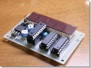
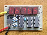
PIC16F88 VOLTMETER PROJECT
PIC16F88 Digital Voltmeter Circuit schematic source C and hex code files:
FILE DOWNLOAD LINK LIST (in TXT format): LINKS-5085.zip
Source: PIC16F88 DIGITAL VOLTMETER CIRCUIT
- What is the maximum voltage the voltmeter can measure?
Up to 20V as stated in the article. - What resolution does the voltmeter achieve?
Practical resolution is about 10 mV. - Which microcontroller is used in the project?
The PIC16F88 microcontroller is used. - How are the 7-segment displays driven?
They are driven dynamically using 74LS47 or 74HC47 BCD-to-7-segment drivers and a 74HC238 digit control decoder. - Does the project include source code and schematic?
Yes, the article provides schematic, C source, and hex code files for download. - How is accuracy improved?
By using a reference voltage and correcting measured values based on the PIC-calculated voltage. - How many ADC conversions are recommended per reading?
The article notes the PIC ADC needs conversion time for the internal sampling capacitor and implies multiple or timed conversions; it mentions muS time for charging the sampling capacitor. - Which port is used to control the displays?
Port B is used to control the displays, and another port is used to read ADC data.