Summary of PIC16F877 UART code and Proteus simulation
This article explains using interrupt-driven UART on the PIC16F877, with C code written for MPLAB using the HI-TECH C compiler and testable in Proteus. It describes TX on RC6, RX on RC7, default 9600 bps, startup transmission of Hello World, and echoing received characters via an interrupt service routine. Downloads include source code and a Proteus simulation.
Parts used in the PIC16F877 UART interrupt example:
- PIC16F877 microcontroller
- Proteus simulation software (for circuit and virtual terminal)
- MPLAB IDE (used to compile and build the project)
- HI-TECH C compiler (v9.83 as used in example)
- Virtual terminal in Proteus (for serial I/O)
- Connections: RC6 (TX) and RC7 (RX) pins
This post answers the question, “How to use interrupt based UART in PIC16F877” ?
Also, using PIC16 simulator (Proteus) you can verify this UART code and change it according to your needs. This code is written in C language using MPLAB with HI-TECH C compiler. You can download this code from the ‘Downloads‘ section at the bottom of this page.
This PIC16F877 microcontroller tutorial provides the interrupt based UART functions which you can easily understand and use. After reading this page you can easily use PIC16F877 serial UART interface.
It is assumed that you know how to blink an LED with PIC16F877 microcontroller. If you don’t then please read this page first, before proceeding with this article.
The following diagram (made in Proteus) shows the PIC microcontroller circuit diagram.
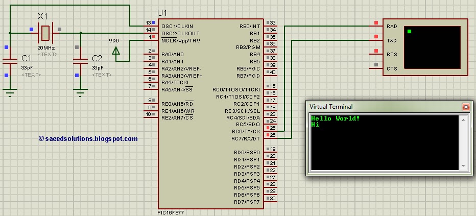
In the above figure, UART baudrate is currently set to 9600 bps, but you can change it to your desired value. RC6 pin is the TX pin and RC7 pin is the RX pin the UART. Whenever a new character is received on the UART, then PIC16F877 goes into interrupt service routine and received character is echoed back.
When code starts to execute then PIC16F877 sends ‘Hello World‘ to virtual terminal. After that PIC16F877 echos back whatever character is sent to it. ‘Hi’ was typed in the virtual terminal after the start up of the simulation in Proteus and PIC16F877 echoed it back.
Code
The code used to set different properties of UART is shown below. (From UART.h file)
Downloads
UART code for PIC16F877 was compiled in MPLAB v8.85 with HI-TECH C v9.83 compiler and simulation was made in Proteus v7.10. To download code and Proteus simulation click here.
For more detail: PIC16F877 UART code and Proteus simulation
- How is UART baud rate set in this example?
The baud rate is set to 9600 bps by default, and can be changed as desired in the code. - Can the UART code be tested without hardware?
Yes, the code is tested and verifiable using Proteus simulation and its virtual terminal. - What pins are used for TX and RX on PIC16F877?
RC6 is the TX pin and RC7 is the RX pin for UART. - Does the PIC16F877 use interrupts for UART reception in this project?
Yes, UART reception triggers an interrupt service routine which handles received characters. - What does the PIC send when the code starts?
On startup the PIC sends Hello World to the virtual terminal. - How does the PIC respond to characters typed in the terminal?
The PIC echoes back any character received via UART from the virtual terminal. - Which tools and versions were used to compile and simulate the project?
The code was compiled in MPLAB v8.85 with HI-TECH C v9.83 and simulated in Proteus v7.10.