Summary of PIC16F877 DIGITAL LOGIC INTEGRATED TEST TTL IC TESTER CIRCUIT
This article describes a TTL IC tester circuit built around the PIC16F877 microcontroller. It enables testing of various digital logic integrated circuits via a computer connection using an RS232 port and MAX232 interface. The system supports different IC sizes through a ZIF socket and utilizes specific software for programming and testing phases, with detailed operational explanations provided in English.
Parts used in the PIC16F877 Digital Logic Integrated Test TTL IC Tester Circuit:
- PIC16F877 Microcontroller
- MAX232 Interface Chip
- RS232 Port
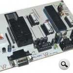
- ZIF Socket
- Shamash Cable
- Computer
- Source ASM Software
- Hex Software
EPE magazine free distribute a project is actually a previous post could be added, but I want to isolate because too different circuit digital logic ICs with that circuit will test you can install on your computer that you… Electronics Projects, PIC16F877 Digital Logic Integrated Test TTL IC Tester Circuit “microchip projects, microcontroller projects, pic16f877 projects,
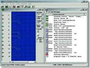
EPE magazine free distribute a project is actually a previous post could be added, but I want to isolate because too different circuit digital logic ICs with that circuit will test you can install on your computer that you program with visual tested as integrated data can be seen
Circuit PIC16F877 based on computer communication MAX232 RS232 port provided for connection ZIF socket, thanks in different sizes integrated, can be tested source asm and hex software’s test phase circuit operating principle and explains in detail (english) also cable Shamash is in
TTL IC TESTER CIRCUIT
PIC16F877 Digital Logic Integrated Test TTL IC tester Circuit schematic source code etc. files
FILE DOWNLOAD LINK LIST (in TXT format): LINKS-7133.zip
Source: PIC16F877 DIGITAL LOGIC INTEGRATED TEST TTL IC TESTER CIRCUIT
- What is the main function of this project?
The project is a TTL IC tester circuit designed to test digital logic integrated circuits. - Can I install this on my computer?
Yes, you can install the program on your computer to test integrated data visually. - How does the circuit connect to the computer?
The circuit uses a computer communication interface based on the MAX232 and an RS232 port. - What type of socket is used for testing different IC sizes?
A ZIF socket is provided to accommodate different sizes of integrated circuits. - Is there software included for testing?
Yes, source asm and hex software are available for the test phase. - Does the article explain how the circuit works?
The article explains the operating principle of the circuit in detail. - What language is the explanation written in?
The detailed explanation is provided in English. - What cable is mentioned for the connection?
The Shamash cable is mentioned as part of the setup. - Where can I download the files?
Files including schematic and source code are available in a ZIP file named LINKS-7133.zip.