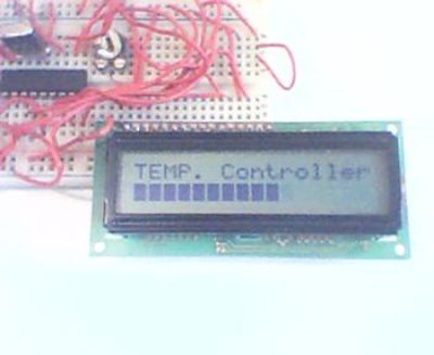
Ever needed to measure temperature and display it? This project details measuring temperature using a temperature sensor ,an ADC and a Microcontroller PIC16f84a with schematics,codes and illustrations. You can also get the following kit, although not based on the pic, which would make your life easier for your future projects.
This project was done fairly long ago, so please excuse the quality of the pictures.
Overview
The Temperature control module was a part of my Final year undergraduate project,which consisted of transmitting data wirelessly.
The module uses an inexpensive 8 bit Temperature Sensor the TMP37 from Analog Devices.
Since the data was analog and the PIC16f84 does not have an analog input,an external ADC had to be used.
Texas Instruments’ TLC549 was chosen for this.The advantage of this ADC was that it could communicate with the microcontroller serially.You may also use similar ADCs from Maxim-IC.
The LCD is a normal 16×2 display which uses the Hitachi Controller HD44780.
The module is breadboarded and not done on a PCB.Schematics are included in appropriate places below.
This site was a great help in building the project.
Mark S. Csele’s PIC Temperature Controller Page
Capabilities of the system:
-Show Current Temperature,Set temperature and Alarm Display.
-Go into Set Mode.
-Increment/Decrement Set Point.
-Enter Set point.
The project is divided into the following subparts:
-The Analog to Digital converter TLC 549 [8 bit]
-The Temperature Sensor TMP37
-The PIC16F84 / PIC16F84a Microcontroller
-Input Buttons
-The Liquid Crystal Display [LCD]
-Temperature Control
-Codes
Note:To follow this project you may need to know to program a PIC,there are some helpful links at the bottom of the page if you are not familiar with it.
The Analog to Digital converter TLC 549 [8 bit]
Description : The TLC549 is an analog-to-digital converter (ADC) integrated circuit built around an 8-bit switched-capacitor successive-approximation ADC. This device is designed for serial interface with a microprocessor or peripheral.
Signals:
The TLC549 has two control lines and one data output line.
They are as follows:
–CS[bar] :: Input signal.The Chip Select signal.When low it selects/activates the chip.When high it disables the chip
–I/O clock :: Input signal.The input/output clock line is used to clock the ADC.
–Data Out :: Output signal.The data out signal clocks out bits into the PIC microcontroller.
For more detail: PIC16F84A Temperature Controller

