Summary of PIC16F84A PWM code and Proteus simulation
This article details generating PWM signals on a PIC16F84A microcontroller using Timer0 interrupts within the C language. It explains initializing Timer0 to produce a 9.1KHz wave with a 50% duty cycle at a 20MHz crystal frequency. The project utilizes MPLAB IDE, HI-TECH C compiler, and Proteus for simulation, allowing users to modify the output pin (RA0) and duty cycle directly in the code.
Parts used in the PIC16F84A PWM Project:
- PIC16F84A microcontroller
- Timer0 module
- 20MHz crystal oscillator
- RA0 pin
- MPLAB v8.85 software
- HI-TECH C v9.83 compiler
- Proteus v7.10 simulator
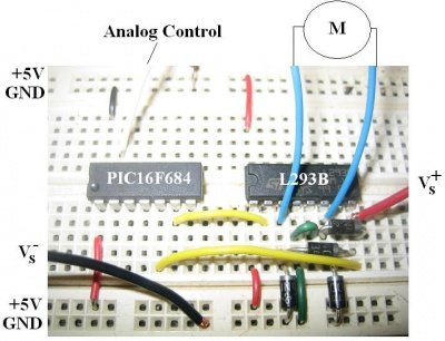
This post provides the PWM code for PIC16F84A microcontroller using timer0. There are many uses for PWM signal, e-g you can control dc motor speed using PWM.
Timer0 is initialized in the start of the main function and using timer0 interrupts, PWM is generated. This code is written in C language using MPLAB with HI-TECH C compiler. You can download this code from the ‘Downloads‘ section at the bottom of this page.
It is assumed that you know how to configure timer0 of PIC16F84A microcontroller. If you don’t then please read this page first, before proceeding with this article.
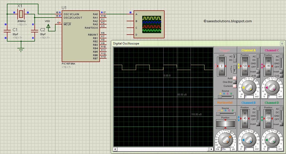
The result of simulating the code in Proteus is shown below.
Here PIC16F84A is running on 20MHz crystal. A PWM wave of 9.1KHz frequency with 50% duty cycle is being generated as shown in the above figure. RA0 pin is being used as PWM_PIN, which you can easily change in the code. Also, you can change PWM duty cycle in the code at any time as well.
Code
The code used to initialize PWM is shown below.
In this InitPWM() function, RA0 pin is made an output, also timer0 is initialized with it’s interrupts enabled. Rest of the PWM generation code is written inside timer0 interrupt service routine code, which is shown below.
Downloads
PWM code using PIC16F84A was compiled in MPLAB v8.85 with HI-TECH C v9.83 compiler and simulation was made in Proteus v7.10. To download code and Proteus simulation click here.
For more detail: PIC16F84A PWM code and Proteus simulation
- How is the PWM signal generated?
PWM is generated using Timer0 interrupts after Timer0 is initialized in the main function. - What programming language is used for the code?
The code is written in C language using the HI-TECH C compiler. - Which pin is used as the PWM output?
The RA0 pin is used as the PWM_PIN, though this can be changed in the code. - What frequency and duty cycle are produced in the simulation?
A PWM wave of 9.1KHz frequency with a 50% duty cycle is generated. - What speed does the PIC16F84A run at in this example?
The microcontroller runs on a 20MHz crystal. - Can the PWM duty cycle be changed dynamically?
Yes, you can change the PWM duty cycle in the code at any time. - What software was used for compilation and simulation?
MPLAB v8.85 was used for compilation and Proteus v7.10 for simulation.