Summary of PIC16F690 Microcontroller Circuit- How to Drive an LED Display
This article demonstrates driving a 7-segment LED display using a PIC16F690 microcontroller from the PIC2 Starter Kit. It explains the device's internal structure, the efficiency of using a microcontroller versus manual control, and details the circuit connections for a common anode display. The guide covers hardware setup, including current-limiting resistors and power supply options via PICkit 2, and provides software configuration for counting from 0 to 9 at a 0.5-second interval using HI-TECH PICC PRO compiler logic.
Parts used in the PIC16F690 Microcontroller Project:
- PIC16F690 microcontroller chip
- PIC2 Starter Kit
- 7 Segment LED Display (Common Anode)
- 330Ω resistors
- PICkit 2 programmer
In this article, we will show how to drive a 7 segment LED Display using a PIC16F690 microcontroller.
This PIC16F690 microcontroller chip is actually a part of the PIC2 Starter Kit, so we will actually be using this starter kit to drive the LED Display.
A 7 Segment LED Display is an electronic device that contains 8 individual LEDs. Each of the LEDs can either be on or off. Depending on which LEDs are lit determines the character which is displayed. The LED display can show any number from 0 to 9. It can also show many alphabetical characters.
In this project, we will use the PIC16F690 microchip contained in the PIC2 Starter Kit to control the 7 segment LED display so that we can light up whichever segments we want to display whatever characters we want in sequence.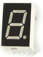
A 7 segment LED display is a valuable electronic device because used in conjunction with other LED displays, it can function as a numerical display, such as time for a clock, a display for a game scoreboard, or any such other numerical display. So it is a very valuable electronic device to know how to operate.
Using a microcontroller to drive an LED display is much more easy and efficient than not. If we did not have a microcontroller to drive an LED, in order to display different numerical values, we would need someone to manually change which turn on or off different LEDs in the LED display. This would be much less efficient than using a microcontroller. When a microcontroller, in this case a PIC16F690 microcontroller, is connected to an LED display, all we need to do to change the software to display different characters. Changing the hardware, which LEDs are lit, is much more complex and time-consuming and, thus, is simply not efficient.
We will now show how to connect and program the PIC16F690 microcontroller to drive an LED display. Specifically, for this circuit, we will drive one LED display, for simplicity, to count from 0 to 0 and then reset back to 0.
Again, a 7 segment LED sipaly is made up of 8 individual LEDs. Thus, the microcontroller needs enough I/O pins to connect to each of the 8 terminals of the 7 segment LED display. It’s the job of the software to light them in the proper order to create the numbers 0 to 9.
For this project, we will use a common anode LED display, which is a display all the anode leads are common and the cathode leads are not. To understand the difference between common anode and common cathode displays, see What is a 7 Segment LED Display.
Schematic
The schematic of the PIC16F590 microcontroller chip connected to the LED display is shown below:
The PIC16F690 can drive an LED directly from an I/O pin because it can output up to 25ma of current. The whole port can supply 200ma in total maximum. We connect 330Ω resistors to the outputs to limit current so that the LEDs don’t receive too much current and burn out. They are safety current-limiting resistors.
The only connections we need is 5 volts of power to the Vdd pin and to have the Vss pin connected to ground. However, if you plug in the PICkit 2 programmer, you can get power from it and, thus, would not have to make power connections. This reduces more connections.
The PIC16F690 has an internal oscillator that we will run at the default speed of 4MHz. The MCLR master clear reset pin will be set to internal mode so we don’t need any external reset circuitry. Those are both setup in the configuration register of the PIC16F690. We control that configuration in the software.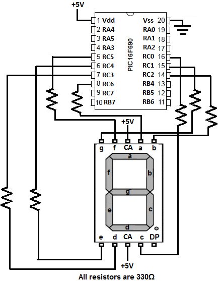
Being that the LED display is common anode, all the anodes are tied together (are common). The cathodes are separate and tie down to ground. For an LED to have a complete circuit and turn on, the LED needs to connect to ground. This will happen if its cathode terminal is connected to ground. Thus, if an LED segment is connected to ground it is on. This is why an LED turns on if it is low. If the LED is connected only to the anode’s positive voltage, it is HIGH and off. This will be important when coding, because a 0 will represent an ON LED and a 1 will represent an OFF LED.
Code to Drive LED Display
The code need to drive an LED display is written for the HI-TECH PICC PRO compiler. This can be done in lite mode.
This will sequence 0 to 9 at a 1/2 second rate. It is a common anode display driven by PortC.
For more detail: PIC16F690 Microcontroller Circuit- How to Drive an LED Display
- What components are required to drive the LED display?
The project uses a PIC16F690 microcontroller from the PIC2 Starter Kit, a common anode 7 segment LED display, and 330Ω safety current-limiting resistors. - Can the PIC16F690 drive the LED directly without extra drivers?
Yes, the chip can output up to 25ma of current per pin and 200ma total, allowing it to drive the LED directly. - How do you prevent the LEDs from burning out?
330Ω resistors are connected to the outputs to limit current and act as safety current-limiting resistors. - Does the project require external power connections if using a programmer?
No, plugging in the PICkit 2 programmer allows the system to receive power from it, reducing the need for separate power connections. - What oscillator speed is configured for this project?
The PIC16F690 uses its internal oscillator set to run at the default speed of 4MHz. - Why does a low signal turn on the LED in this specific circuit?
Because it is a common anode display, connecting a cathode terminal to ground completes the circuit, so a 0 represents an ON state. - Which compiler is used for the code in this project?
The code is written for the HI-TECH PICC PRO compiler and can be done in lite mode. - What sequence does the display show in the example?
The code sequences numbers from 0 to 9 at a rate of 1/2 second before resetting back to 0.