
Summary of PIC16F1847 and AR1010 Based FM Radio Music Box
This project details the construction of a portable Digital FM Radio using a PIC16F1847 microcontroller and an AR1010 receiver module. The author chose the PIC chip over Arduino due to existing inventory, despite the prevalence of Arduino tutorials. The device features a MAX7219 7-segment display for frequency output and a PAM8403 audio amplifier. It is powered by a salvaged 18650 battery via a boost converter, housed in a custom 3D-printed enclosure, and controlled by three push buttons.
Parts used in the Digital FM Radio Box:
- PIC16F1847 Microcontroller
- AR1010 FM Radio Receiver Module
- MAX7219 8 Digit 7 Segment Led Module
- PAM8403 5V DC Audio Amplifier Board
- 3V to 5V 1A Step Up Module USB Charger Boost Converter
- 18650 Battery (salvaged from old laptop)
- 3 pcs. Push button micro switches
- AMS1117-3.3 Voltage Regulator
- 4.7Kohm Resistors
- 10uf / 16v electrolytic capacitor
- Custom 30mm x 30mm perf board
- 3D Printed Box Enclosure
This is my first Instructable post. I made a Digital FM Radio box using this cheap AR1010 FM Radio receiver module that I bought from Ebay and a PIC16F1847 Microcontroller from MICROCHIP. Why PIC’s? Why not use Arduino? Because i have bunch of these IC’s stocked in the parts bin. And also because most of the Digital FM Radio instructables and tutorials use the arduino.
Let’s Make it…..
Step 1: Parts and Tools Needed…
The Basic parts are the Following:
- The Brain – Microchip Pic16F1847
- Digital FM Radio Receiver – AR1010 Module
- Display – MAX7219 8 Digit 7 Segment Led Module
- Audio Amplifier – PAM8403 5V DC Audio Amplifier Board 2 Channel 2*3W Volume Control
- Power/Charging – 3V to 5V 1A Step Up Module USB Charger Boost Converter w/ 1pc. 18650 battery salvaged from old laptop battery pack.
- Interface – 3 pcs. push button micro switches
- 3D Printed Box Enclosure – STL files link here
Tools to Use:
- Soldering Iron
- Long Nose Pliers
- Digital Multi tester
- Exacto Knife
- Cutter Plier
- Glue Gun
- 3D Printer
- Microchip PICKIT 3 Programmer/Debugger
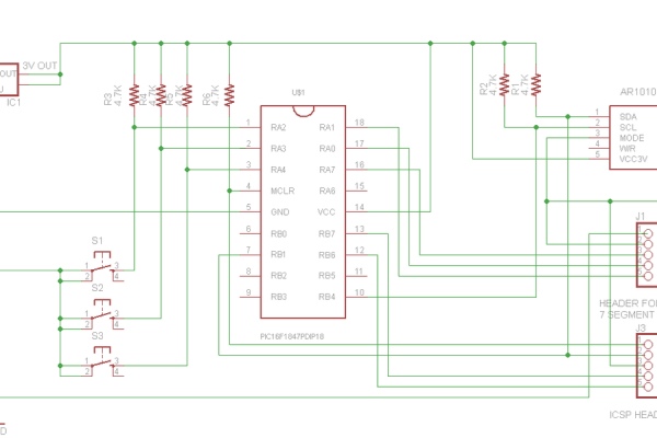
The Schematic is drawn using the Free version of Autodesk Eagle PCB design software.
The parts list for the main board are the following:
1 pc. PIC16F1847 MCU PDIP-18
1 pc. AMS1117-3.3 Voltage Regulator SOT223
6 pcs. 4.7Kohm / 0.5 watt Resistors
1pc. 10uf / 16v electrolytic capacitor
All these parts are mounted on a custom cut 30mm x 30mm single sided perf board to fit it inside the casing. The PIC Mcu is mounted on the top side the board. The AMS1117-3.3 SMD regulator and the AR1010 module are soldered on the copper side .
There is no external Oscillator because i used the internal 32 mhz clock of the PIC16F1847 MCU. I didn’t use any headers and connectors to connect the modules, they are soldered with jumper wires. The headers are for serial debugging and ICSP programming.
Step 3: CODE
The code is written and compiled using the Code Limited version of the MikroC for PIC.
I used the Ar1010 Arduino Library of adamjansch/AR1010lib and ported it to be compatible with the MikroC for PIC IDE.
I wrote my own Max7219 library.
Step 4:
Updated the Source File to include the MAX7219 library…
Attachments
Source: PIC16F1847 and AR1010 Based FM Radio Music Box
-
Why did the author choose a PIC microcontroller instead of Arduino?
The author had a stockpile of these ICs in their parts bin and noted that most existing digital FM radio tutorials use Arduino. -
What software was used to write and compile the code?
The code was written and compiled using the Code Limited version of MikroC for PIC. -
How was the AR1010 library adapted for the PIC microcontroller?
The author used the Ar1010 Arduino Library by adamjansch/AR1010lib and ported it to be compatible with the MikroC for PIC IDE. -
Does this design require an external oscillator?
No, the design uses the internal 32 mhz clock of the PIC16F1847 MCU. -
How are the modules connected to the main board?
The modules are soldered together using jumper wires rather than headers and connectors. -
What tools are required to build this project?
Tools include a soldering iron, long nose pliers, digital multi tester, exacto knife, cutter plier, glue gun, 3D printer, and a Microchip PICKIT 3 Programmer/Debugger. -
What type of power source is used for the radio?
A 18650 battery salvaged from an old laptop battery pack is used in conjunction with a 3V to 5V step-up USB charger boost converter.
