
Summary of PIC16C63 Midi controlled Light dimmer
This article describes two PIC16C63 microcontroller projects: a MIDI-controlled light dimmer and a Pinewood Derby race timer. The dimmer system uses MIDI ports, channels, and devices to control four lights and a relay per box via DIP switches, supporting daisy-chaining. It integrates with Cakewalk software or standard RS-232 interfaces. The race timer features a starting gate switch, finish line detectors for four lanes, an LCD display, and planned serial output for timing data.
Parts used in the MIDI Light Dimmer:
- PIC16C63 Microcontroller
- MIDI Input Connector
- MIDI Output Connector
- DIP Switch
- Four Lights
- One Relay
Parts used in the Pinewood Derby Race Timer:
- PIC16C63 Microcontroller
- Starting Gate Switch
- Finish Line Light Detectors (4 lanes)
- 2 Line 40 Character LCD
- RS232 Serial Port Interface
This is Ver2.0 of a finished project.
I usually do projects about the same way every time. Product definition (10 min), Code outline (10 min), Schematic generation, Build prototype, Write code all at one sitting (This one took about 6 hours), Take a copy of the above file, and delete all but a small section. Debug the section, and put it back into the original file. Repeat with other chunks of code until done. Test the program as a whole, Mass produce and be famous (never got to this last step yet).
Files in MIDI.ZIP
MIDI20.C Source code for Midi Light dimmer
MIDI.SCH Schematic in OrCad Version IV (Dos version)
MIDI.LIB Library file for OrCad Schematic
MIDI.DXF Schematic in DXF Format
MIDI_SCH.PDF Schematic in Postscript format…. Copy to postscript printer
Download “MIDI.ZIP” PIC16C63 C source code and schematics.
View Schematic for the MIDI light dimmer (PDF File).
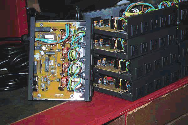
View Photo of finished product.
MIDI Nomenclature is as difficult to describe as it is to spell.
Use the terms Port, Channel, Device, and Box like this. You can have lots of MIDI ports (Connectors) on a machine. Each MIDI PORT can have 16 CHANNELS of 127 DEVICES (notes) each. Each light dimmer box consumes 5 DEVICEs: 4 lights and one relay.
As it is, the box has a MIDI interface. There’s an input connector and an output connector. The boxes’ output connector goes downstream to the next boxes’ input connector. There’s a DIP switch in each box to select which of the 16 channels the box will respond to, and what device the first light will respond to. The four lights and the relay will respond to four consecutive device addresses. So… With the dipswitch, you can set a box to be on channel 5, and use devices 32 thru 36. The first light will respond to device 32, the next light device 33, the next 34, and the last 35. The relay will then use device 36. You can connect another box to the first box’s output connector, and set it to respond to channel 5 devices 37-41, (or any channel, any device).
Cakewalk is a MIDI sequencer / editor and it is good. You can just draw the desired intensity of a particular light by drawing a volume envelope of a single note. If you’re in a stage act, and already have Cakewalk doing the sound, that’s the way to go. The existing design can be modified to use standard baud rates, and the RS-232 Electrical interface. Then you can just fire off commands via RS-232. Cakewalk would be a little difficult to interface to if you just wanted to make a home lighting system that responds to opening doors and time of day. For that you just wip something up in Visual basic using standard com port commands.
PIC “Pinewood Derby” style race timer.
PIC based “Pinewood derby style” race track timer. One switch closure starts the race and initiates end of race process. That switch is mounted to the starting gate. When the gate snaps open, the cars start rolling. The gate stays open until the race is over. The act of closing the gate, clears the timers, sets the state machine, and process flags to be ready for the next race. Digital inputs to indicate finish line crossings, one for each of four lanes. A digital high is output by the track when a car shadows the light detector at the finish line. This timer detects the rising edge of this signal. 11 bits of output are consumed by the 8 bit interface to a 2 line, 40 char LCD. There’s plans for a RS232 output to squirt the race times out a serial port. The timer is a great use during car tune-up. It doesn’t seem to add much to a race.
For more detail: PIC16C63 Midi controlled Light dimmer
- How many devices does each light dimmer box consume?
Each box consumes five devices consisting of four lights and one relay. - Can multiple dimmer boxes be connected together?
Yes, the output connector of one box connects downstream to the input connector of the next box. - What software is recommended for controlling the lights via MIDI?
Cakewalk is suggested as a MIDI sequencer editor that allows drawing volume envelopes for light intensity. - How are channel and device addresses selected for a dimmer box?
A DIP switch in each box selects the specific channel and the starting device address for the lights and relay. - What interface modification allows using standard baud rates instead of MIDI?
The design can be modified to use standard baud rates and the RS-232 electrical interface. - How does the race timer detect the start of a race?
It detects the closure of a switch mounted to the starting gate which snaps open when cars begin rolling. - What signal does the race timer look for at the finish line?
The timer detects the rising edge of a digital high signal generated when a car shadows the light detector. - How many lanes can the race timer monitor simultaneously?
The system supports digital inputs for four separate lanes.
