Summary of PIC16C622 MICROCONTROLLER MEASURING THE RESISTANCE CAPACITOR RC METER CIRCUIT
This article describes the PICMETER, a circuit based on the PIC16C622 microcontroller that measures resistance (1Ω to 999Ω) and capacitance (1nF to 999nF). It utilizes an exponential charge waveform comparison method instead of traditional integrating converters. The system connects to a PC via assembly language software prepared in Visual Basic to display measured values.
Parts used in the PICMETER:
- PIC16C622 microcontroller
- Resistors for measurement range 1Ω to 999Ω
- Capacitors for measurement range 1nF to 999nF
- PC computer interface
- Visual Basic software
- Assembly language code
Based on PIC16C622 microcontroller circuit between 1Ω 999Ω resistance measurement between 1nF to 999 nF capacitor measurement yapılabiliry computer’s connection to the controller software pc software with assembly prepared with Visual Basic. PIC16C622 and application circuit microchip application notes… Electronics Projects, PIC16C622 Microcontroller Measuring the Resistance Capacitor RC Meter Circuit “microchip projects, microcontroller projects,

Based on PIC16C622 microcontroller circuit between 1Ω 999Ω resistance measurement between 1nF to 999 nF capacitor measurement yapılabiliry computer’s connection to the controller software pc software with assembly prepared with Visual Basic. PIC16C622 and application circuit microchip application notes all the details about the original formula is given.
RESISTANCE, CAPACITOR METER CIRCUIT SCHEMATIC
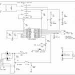
The application circuit, called PICMETER, uses a PIC16C622 as a resistance and capacitance meter. The PICMETER uses a variation of the single-slope integrating converter. The linear slope and integrator of Figure 13 are replaced with the exponential charge waveform of an RC. The charge time of a known component is compared against the charge time of an unknown component to determine the value of the unknown component.
A schematic of the PICMETER is shown in Figure 16. All reference designators cited in this section refer to this schematic. Results are transmitted to a PC which displays the value measured.
PIC RC meter Circuit files:
FILE DOWNLOAD LINK LIST (in TXT format): LINKS-9194.zip
Source: PIC16C622 MICROCONTROLLER MEASURING THE RESISTANCE CAPACITOR RC METER CIRCUIT
- What components does the PICMETER measure?
The circuit measures resistance between 1Ω and 999Ω and capacitance between 1nF and 999nF. - How does the PICMETER determine unknown component values?
It compares the charge time of a known component against the charge time of an unknown component using an exponential charge waveform. - Can the PICMETER connect to a computer?
Yes, results are transmitted to a PC which displays the measured value. - What software is used to control the controller?
Assembly language prepared with Visual Basic is used for the PC software connection. - Does the circuit use a single-slope integrating converter?
No, it uses a variation where the linear slope and integrator are replaced with an exponential charge waveform of an RC. - Where can I find the schematic for this circuit?
A schematic of the PICMETER is shown in Figure 16 of the original document. - Is there source code available for download?
Yes, PIC RC meter Circuit files are available in a TXT format download link list named LINKS-9194.zip. - What is the specific name of this application circuit?
The application circuit is called PICMETER.