PIC10 TB085 HDL Sample using PIC10F206 with Proteus Simulation

Summary of PIC10 TB085 HDL Sample using PIC10F206 with Proteus Simulation


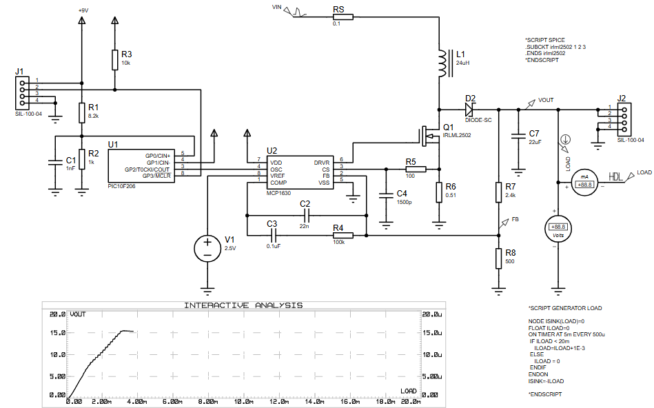
Summary: This PIC10 TB085 HDL Sample uses a PIC10F206 to generate 250 kHz control pulses for an MCP1630 DC/DC controller. Firmware implements software soft start, undervoltage lockout via the internal comparator, over-temperature shutdown, and auto-restart. Simulated in Proteus VSM, the minimal-pin design demonstrates protection handling and pulse generation for power-supply applications and learning embedded power control techniques.

Parts used in the PIC10 TB085 HDL Sample:

  • PIC10F206 microcontroller
  • MCP1630 DC/DC controller
  • Inductor (24 µH)
  • MOSFET IRLML2502
  • Schottky diode
  • Resistors (feedback, timing, filtering)
  • Capacitors (feedback, timing, filtering)
  • Temperature sensor (digital output)
  • Linear regulator for Vdd (+2.5 to 5.5 V)
  • Proteus VSM simulation environment (for simulation)
Introduction

This PIC10 TB085 HDL Sample is a compact yet powerful microcontroller project designed to generate high-frequency control pulses for a DC/DC power supply. Built around the PIC10F206, the project demonstrates how minimal hardware and firmware can implement advanced features like soft start, undervoltage lockout, and over-temperature shutdown.
Simulated entirely in Proteus, this project is ideal for learning embedded systems, practical electronics, and firmware-driven power control techniques. It serves as a solid reference design for engineers working with small PIC devices and switch-mode power supplies.

How the Project Works (Overview)

The PIC10F206 acts as a pulse generator for the MCP1630 DC/DC controller. It produces a 250 kHz switching signal on one of its GPIO pins. During startup, the firmware gradually increases pulse activity using a soft-start algorithm, preventing inrush current.
The microcontroller continuously monitors supply voltage and temperature inputs. If undervoltage or overheating is detected, pulse generation stops automatically and restarts only when conditions return to normal.

Block Diagram / Workflow Explanation

  1. Power-up Initialization

    • GPIO configured

    • Comparator enabled

    • Watchdog timer set

  2. Voltage Check

    • Comparator verifies scaled input voltage on GP0

    • Low voltage prevents startup

  3. Soft Start Sequence

    • Pulse table gradually ramps duty over ~5 ms

    • Ensures smooth DC/DC startup

  4. Normal Operation

    • Continuous 250 kHz pulse output on GP2

    • Watchdog serviced regularly

  5. Protection Handling

    • Undervoltage → pulses disabled

    • Over-temperature → pulses disabled

    • Auto-restart with soft start

Key Features

  • Software-based soft start control

  • 250 kHz pulse generator for MCP1630

  • Undervoltage lockout using internal comparator

  • Over-temperature shutdown via digital sensor input

  • Active-low external shutdown using MCLR

  • Fully simulated in Proteus VSM

  • Extremely low pin-count design using PIC10 family

Components Used

  • PIC10F206 microcontroller

  • MCP1630 DC/DC controller

  • Inductor (24 µH)

  • MOSFET (IRLML2502)

  • Schottky diode

  • Resistors and capacitors (feedback, timing, filtering)

  • Temperature sensor (digital output)

  • Proteus VSM simulation environment

Applications

  • DC/DC power supply controllers

  • Embedded power management systems

  • Battery-powered electronics

  • Educational PIC microcontroller projects

  • Soft-start and protection logic demonstrations

Explanation of the Code (High-Level)

The firmware is written in MPASM and optimized for the PIC10F206. It uses GPIO bit-toggling to generate high-speed pulses instead of hardware PWM.

  • Initialization Section
    Configures GPIO direction, comparator, watchdog timer, and clears registers.

  • Soft Start Routine
    A pulse table progressively increases the number of pulses per cycle, smoothly ramping output power.

  • Main Pulse Loop
    Continuously generates pulses while monitoring voltage and temperature inputs.

  • Protection Routines
    Separate handlers manage undervoltage and over-temperature events, safely shutting down and restarting the system.

Source Code

Download
Name	Function                                                    *
;* 1	GP0	externally scaled supply voltage                            *
;* 2 	Vss	Ground                                                      *
;* 3 	GP1	digital output of temperature sensor                        *
;* 4	GP2 	250 kHz output for MCP1630                                  *
;* 5	Vdd	+2.5 to 5.5 Volts Power Supply (linear regulator)           *
;* 6	GP3 	MCLR input for !Shutdown control 

Proteus Simulation

In Proteus, the PIC10F206 generates a clean 250 kHz pulse train on GP2, driving the MCP1630 controller. During startup, the output voltage ramps smoothly due to the software soft start. When undervoltage or temperature faults are injected, the simulation clearly shows pulse shutdown and controlled restart behavior.

(FAQs)

1. Can this project run without Prote

Yes, it is designed for real hardware, but Proteus helps visualize behavior safely.

2. Why is software PWM used instead of hardware PWM?

PIC10F206 has no hardware PWM module; GPIO toggling is used instead.

3. Can I change the switching frequency?

Yes, by modifying instruction timing and loop structure.

4. How is undervoltage detected?

Using the internal comparator on GP0 with scaled input voltage.

5. Is the soft start duration adjustable?

Yes, by modifying the pulse table and delay counters.

6. Can another PIC10 device be used?

Only compatible PIC10 devices with similar pin functions.

7. What happens during over-temperature?

Pulse generation stops until temperature input returns high.

Conclusion

The PIC10 TB085 HDL Sample is an excellent example of how a tiny PIC10F206 can control complex power-supply behavior using smart firmware. With soft start, fault protection, and high-frequency pulse generation, this project is a valuable learning resource for anyone exploring embedded systems, Proteus simulation, and efficient microcontroller projects.

Quick Solutions to Questions related to the PIC10 TB085 HDL Sample:

  • Can this project run without Proteus?
    Yes, it is designed for real hardware, but Proteus helps visualize behavior safely.
  • Why is software PWM used instead of hardware PWM?
    PIC10F206 has no hardware PWM module; GPIO toggling is used instead.
  • Can I change the switching frequency?
    Yes, by modifying instruction timing and loop structure.
  • How is undervoltage detected?
    Using the internal comparator on GP0 with a scaled input voltage.
  • Is the soft start duration adjustable?
    Yes, by modifying the pulse table and delay counters.
  • Can another PIC10 device be used?
    Only compatible PIC10 devices with similar pin functions.
  • What happens during over-temperature?
    Pulse generation stops until the temperature input returns high.
  • What pin provides the 250 kHz output?
    GP2 provides the 250 kHz output for the MCP1630.

About The Author

Ibrar Ayyub

I am an experienced technical writer holding a Master's degree in computer science from BZU Multan, Pakistan University. With a background spanning various industries, particularly in home automation and engineering, I have honed my skills in crafting clear and concise content. Proficient in leveraging infographics and diagrams, I strive to simplify complex concepts for readers. My strength lies in thorough research and presenting information in a structured and logical format.

Follow Us:
LinkedinTwitter