PICCLOCK using PIC16F84A with Proteus Simulation

Summary of PICCLOCK using PIC16F84A with Proteus Simulation


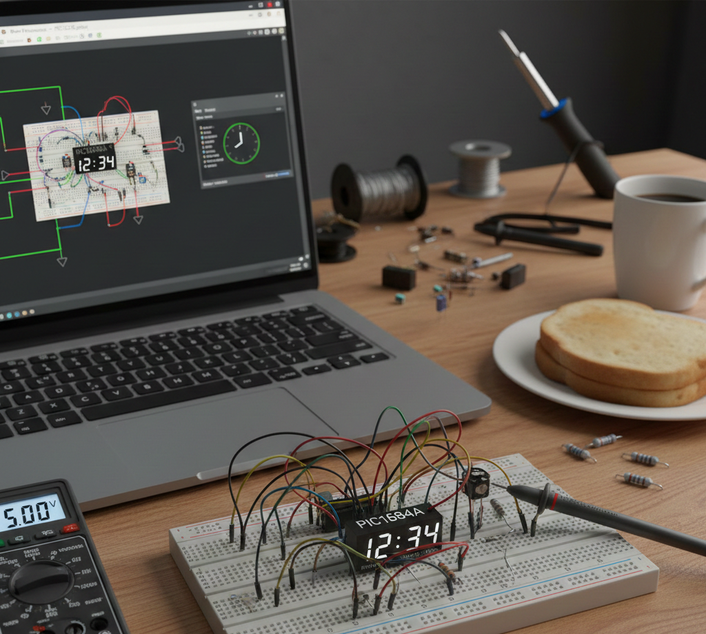
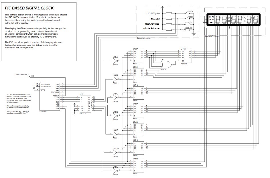
This project implements a fully simulated PIC16F84A-based digital clock in Proteus VSM, featuring interrupt-driven timekeeping, 12/24-hour modes with AM/PM, manual hour/minute adjustment via push buttons, binary-to-BCD conversion for multi-digit displays, and firmware written in MPASM. It demonstrates timing, interrupts, BCD conversion, and display interfacing useful for embedded systems learning without physical hardware.

Parts used in the PICCLOCK using PIC16F84A with Proteus Simulation:

  • PIC16F84A microcontroller
  • Push buttons (Time Set, Hour Set, Minute Set, Mode Select)
  • Digital display interface (BCD-driven)
  • External time base signal (provided in Proteus)
  • Proteus VSM simulation environment

Introduction

This project demonstrates a fully working PIC-based digital clock built around the PIC16F84A microcontroller using Proteus simulation.
The clock tracks hours, minutes, and seconds, supports 12-hour and 24-hour formats, and allows real-time time adjustment using push buttons.
It’s a solid microcontroller project for learning timekeeping, interrupts, BCD conversion, and display interfacing in embedded systems.
Because everything runs inside Proteus, it’s ideal for practical electronics learning without physical hardware.
This project is especially useful for understanding firmware-driven clocks, timing logic, and digital display control.

PIC microcontroller digital clock
Illustrative View of the Concept.

How the Project Works (Overview)

The PIC16F84A uses an external time base to generate periodic interrupts. Each interrupt represents a fixed time tick, which the firmware accumulates to form seconds, minutes, and hours.
The internal logic updates time counters, converts binary values to BCD, and drives a multi-digit display interface.
User input switches allow toggling between 12-hour / 24-hour modes and setting hours or minutes manually.
All timing, display refresh, and user interaction are handled entirely in firmware.

Block Diagram / Workflow Explanation

  1. Time Base Interrupt (RB0/INT)
    Generates periodic ticks used for timekeeping.

  2. Tick Counter
    Groups ticks into half-seconds and full seconds.

  3. Time Counters
    Separate registers track seconds, minutes, and hours.

  4. Mode Logic
    Handles 12h/24h format and AM/PM state.

  5. User Input Handling
    Buttons allow time setting and format selection.

  6. Binary to BCD Conversion
    Converts time values for display output.

  7. Display Interface
    BCD digits are strobed to the display hardware.

Key Features

  • Real-time digital clock using PIC16F84A

  • Interrupt-driven timekeeping

  • 12-hour and 24-hour display modes

  • AM/PM indicator handling

  • Manual hour and minute setting

  • Binary-to-BCD conversion using lookup table

  • Fully simulated in Proteus VSM

  • No external programming hardware required

Components Used

  • PIC16F84A microcontroller

  • Push buttons (Time Set, Hour Set, Minute Set, Mode Select)

  • Digital display interface (BCD-driven)

  • External time base signal (Proteus)

  • Proteus VSM simulation environment

Applications

  • Digital wall clocks

  • Embedded timekeeping modules

  • Learning interrupt-based timing

  • Educational embedded systems labs

  • Firmware design practice

  • BCD display interfacing projects

Explanation of Code (High-Level)

The firmware is written in MPASM assembly and organized into clear functional sections:

  • Initialization configures ports, registers, and interrupts.

  • Interrupt Service Routine processes time ticks and updates counters.

  • Mode Handling Routines manage 12h/24h logic and AM/PM transitions.

  • Time-Setting Logic allows user-controlled hour and minute changes.

  • Display Routines convert binary time values to BCD and strobe them out.

  • Lookup Table efficiently converts binary values to BCD digits.

The design ensures accurate timing while allowing safe user interaction without corrupting time data.

Source Code

Download
              LIST    p=16F84A ; PIC16F84AA is the target processor

              #include "P16F84A.INC" ; Include header file

              CBLOCK 0x10   ; Temporary storage
                 state
                 secs
                 mins
                 hours
                 ticks
                 idc
                 bcd
              ENDC

Proteus Simulation

In Proteus, the clock runs in real time, updating seconds, minutes, and hours automatically.
Button presses allow switching display formats and adjusting time values during simulation.
The simulation pauses, resumes, and debug windows can be used to inspect internal registers and timing behavior, making it ideal for learning and troubleshooting.

(FAQs)

1: Can this project run on real hardware?

Yes, with the same wiring and clock source used in the Proteus schematic.

2: Why use interrupts instead of delays?

Interrupts ensure accurate timing without blocking other operations.

3: Can I replace the PIC16F84A with another PIC?

Yes, but port mapping and configuration registers may need changes.

4: How is 12-hour mode handled?

The firmware tracks AM/PM state and adjusts hour values accordingly.

5: Can I add seconds setting?

Yes, by extending the time-set logic in the code.

6: Why is BCD used for display?

BCD simplifies driving multi-digit decimal displays.

7: Does this require an external RTC?

No, timing is handled entirely in firmware.

Conclusion

This PICCLOCK using PIC16F84A with Proteus Simulation is an excellent hands-on project for mastering embedded timekeeping, interrupts, and display control.
It offers clear learning value for anyone exploring microcontroller projects, Proteus simulation, and real-world firmware design.
A compact, well-structured project that builds strong embedded systems fundamentals.

Quick Solutions to Questions related to PICCLOCK using PIC16F84A with Proteus Simulation:

  • Can this project run on real hardware?
    Yes, with the same wiring and clock source used in the Proteus schematic.
  • Why use interrupts instead of delays?
    Interrupts ensure accurate timing without blocking other operations.
  • Can I replace the PIC16F84A with another PIC?
    Yes, but port mapping and configuration registers may need changes.
  • How is 12-hour mode handled?
    The firmware tracks AM/PM state and adjusts hour values accordingly.
  • Can I add seconds setting?
    Yes, by extending the time-set logic in the code.
  • Why is BCD used for display?
    BCD simplifies driving multi-digit decimal displays.
  • Does this require an external RTC?
    No, timing is handled entirely in firmware.
  • How does the firmware generate seconds and minutes?
    An external time base generates periodic interrupts; firmware accumulates ticks into seconds, minutes, and hours.

About The Author

Ibrar Ayyub

I am an experienced technical writer holding a Master's degree in computer science from BZU Multan, Pakistan University. With a background spanning various industries, particularly in home automation and engineering, I have honed my skills in crafting clear and concise content. Proficient in leveraging infographics and diagrams, I strive to simplify complex concepts for readers. My strength lies in thorough research and presenting information in a structured and logical format.

Follow Us:
LinkedinTwitter