Summary of PIC MCU and Python Serial Communication
Summary: This project demonstrates serial communication between a PIC16F877A microcontroller and Python using a USB-TTL converter. Python sends a null-terminated string to the PIC, which receives characters via an interrupt-driven UART routine, stores them, compares the received string to a target value, and toggles an LED on match. Hardware, software setup, and wiring (TX/RX/GND) plus example Python and CCS C code are provided.
Parts used in the PIC MCU and Python Serial Communication:
- PIC16F877A microcontroller (or equivalent PIC MCU)
- USB to TTL converter (TX, RX, GND)
- MCU programmer (K150 programmer, PicKit 2/3, or similar)
- Computer (for Python and MCU IDE)
- Python IDE (example: PyCharm)
- MPLAB X IDE with CCS C compiler (for MCU programming)
- LED (connected to PIN_D0)
- Wires for TX/RX/GND connections
Hello, guys! In this project I will try to explain my experiments on PIC MCU and Python serial communication. Over the internet, there are many tutorials and videos on how to communicate with PIC MCU over virtual terminal which is very useful. However, in my main project one of the requirements is to establish serial communication between PIC MCU and Python which I couldn’t find good tutorial. So, let’s get started 🙂
Step 1: What Do We Need?
So, first of all let’s see what we need. In terms of hardware:
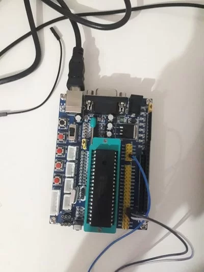
- Surely, PIC MCU which is in my case PIC16f877a (You don’t need that board. This is in order to simplify some dirty connections)
- USB to TTL converter in order to communicate with PIC MCU over USB port by using TX and RX pins.
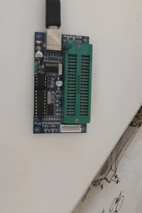
- MCU programmer which is in my case K150 programmer, but you can use PicKit 2,3 or anything else.
- And finally a computer 🙂
In terms of software:
- An IDE in order to write python code which is in my case Pycharm, but you can use regular Python IDE also.
- An environment for programming the MCU which is in my case MPLAB X IDE with CCS C compiler.
Step 2: Hardware Connections
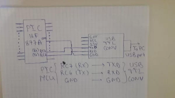
In the picture attached hardware connections are given which are between PIC MCU and USB TTL converter as below:
RC7 (RX) —————> TXD
RC6 (TX) —————> RXD
GND —————-> GND
You don’t need to connect VCC pin of the USB TTL converter (However, if you want you can do). These 3 connections are quite enough.
Step 3: Python Software
Let’s start to write software for Python side which will be transmitter in our case, because it will send the string to the MCU.
import serial #import serial library
data = '24'  #data that we will send
data = a+'\0'
ser = serial.Serial('COM17', baudrate=9600, timeout=1)  #connect to the port
ser.write(a.encode())  #send the data
First of all serial library is imported in order to use its futures. We want to send an example string data in order to confirm in MCU code that we accepted it. I want here to note one thing. This is why we added ‘\0’ to the string. This is because, on the MCU side it is impossible to read the string totally. It is read character by character. So, we want to know the end of the string in order to stop reading. So, we add ‘\0’ to the string which indicates the end of the string. Then we connect to the port that is connected to the MCU. You can determine that port by searching in ‘Device Manager’. So, be careful that you are on the same port. After all, we send the data to the MCU. “.encode()” should be added to the string data in order to be able to send it to the receiver.
Step 4: Microcontroller Software
So, let’s see our code for MCU. First of all I want to show you the “config.h” file’s inside which is not required, but I did it for simplicity. Here just change frequency of your MCU.
#ifndef CONFIG_H
#define	CONFIG_H#include <16F877A.h>
#device ADC=16#FUSES NOWDT                    //No Watch Dog Timer
#FUSES NOBROWNOUT               //No brownout reset
#FUSES NOLVP                    //No low voltage prgming, B3(PIC16) or B5(PIC18) used for I/O#use delay(crystal=6000000)
Now let’s see the main code:
#include <config.h>#include <string.h>
#use rs232 (baud=9600, xmit=pin_C6, rcv=pin_C7, parity=N, stop=1)#define LED_RED PIN_D0

char inp;
char cmp_[]="24";
char buffer[3];#int_rda
void serial_communication_interrupt()
{
    disable_interrupts(int_rda);
    unsigned int i = 0;

    inp = getc();
    putc(inp);
    while(inp != '\0')
    {
        buffer[i] = inp;
        inp = getc();
        putc(inp);
        i++;
    }
}void main(void) {
    set_tris_d(0x00);
    output_d(0xFF);

    enable_interrupts(GLOBAL);

    while(1)
    {
        enable_interrupts(int_rda);
        if(strcmp(buffer, cmp_) == 0)   output_low(LED_RED);
        else                                          output_high(LED_RED);
    }
}
At the beginning we include string library which we will be helpful in string operations which in our case is string compare operation (strcmp). So, our purpose in this code is to turn on the led connected to the pin D0 if the transmitted value is the same as our given value which is “cmp_” equals to “24”.
First of all we enable interrupt “rda” which will cause interrupt when data is transmitted.
Secondly, let’s look inside ISR (interrupt service routine) which is called “serial_communication_interrupt”. Inside we firstly disable interrupt flag in order to read the received value and cause interrupt further. After that we read the string character by character until reaching ‘\0’. While reading inside string we also write each char to the buffer in order to get received string.
At the end, we again come inside while. Here we compare our buffer string which is received string and cmp_ string in order to see whether we get the string correctly. If they are equal then I turn on led, otherwise turn off.*
*In code I did reverse because my board inverts the D port pin values. In your code change it to:
if(strcmp(buffer, cmp_) == 0)   output_high(LED_RED);
else                                          output_low(LED_RED);
Finally, compile it and upload to your MCU and then run code in Python. You should see led turn on.
Step 5: Conclusion
We have finished one task successfully. I hope that it will be useful for you. If you have any question, please don’t hesitate to ask 🙂 Until next project.
Attachments
Source: PIC MCU and Python Serial Communication
- What hardware is needed to communicate PIC MCU with Python?
Required hardware includes a PIC MCU (example PIC16F877A), a USB to TTL converter (TX, RX, GND), an MCU programmer (K150, PicKit 2/3, etc.), and a computer. - What software is needed for this project?
Needed software includes a Python IDE (example PyCharm) and an MCU programming environment (MPLAB X IDE with CCS C compiler). - How should the PIC and USB-TTL be connected?
Connect RC7 (RX) to TXD, RC6 (TX) to RXD, and GND to GND. VCC on the USB-TTL is optional. - How does the Python code send data to the PIC?
Python uses the serial library to open the COM port at 9600 baud, appends a null terminator to the string, encodes it, and writes it via ser.write. - Why is a null character added to the transmitted string?
The null character marks the end of the string so the PIC can detect when to stop reading characters received one by one. - How does the PIC firmware receive and store the string?
An interrupt on receive data available (rda) reads incoming characters with getc in the ISR, echoes them with putc, stores them into buffer until a null terminator is received. - How is the received string used to control the LED?
The main loop compares the received buffer with the target string cmp_ (24) using strcmp; on match the code toggles PIN_D0 to turn the LED on or off. - Do I need to connect the USB-TTL VCC pin?
No, VCC is not needed for communication; only TX, RX, and GND are required, though you may connect VCC if desired.