Summary of PIC Analog to Digital Converter C Programming
This article explains how to program the PIC16F690 microcontroller's 10-bit ADC using HITECT PICC-Lite C. It details configuring registers (ADCON0, ADCON1) to read analog voltage from a trimpot and control LED speed via a running light effect. The tutorial covers port initialization, code implementation in MPLAB IDE, and downloading the program using a PICKit2 programmer on the PICJazz learning board.
Parts used in the PIC Analog to Digital Converter Project:
- PIC16F690 microcontroller
- HITECT PICC-Lite compiler
- PICJazz 16F690 learning board
- Microchip MPLAB IDE
- PICKit2 programmer
- LEDs
- User trimpot
- User switch
The PIC16F690 microcontroller is one of Microchip midrange 8-bit microcontroller that has a build in 10-bit resolution of Analog to Digital Converter (ADC) peripheral. The ADC is one of the important features that enable us to digitize our analog world. Usually we use the electronic sensor to convert the analog value to the voltage level value. Some of the basic sensor such as LDR (Light Dependent Resistor) is used for measuring the light intensity or NTC (Negative Temperature Coefficient) a special resistor for measuring the temperature.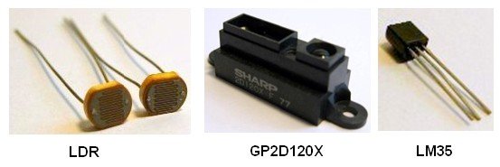
Today many manufactures produce sophisticated sensors for specific task such as sharp GP2D120X is use for distance measurement, National Semiconductor LM35 for precision centigrade temperature sensor, HS12 humidity sensor from GE, TGS2442 carbon monoxide gas sensor from Figaro and many more. Therefore before we can use all of these cool sensors we have to learn the basic of how to use ADC peripheral inside the PIC 16F690 microcontroller.
On this tutorial we will learn how to program the Microchip PIC microcontroller for reading the analog signal using HITECT PICC-Lite C compiler. We will use the PICJazz 16F690 learning board (PICJazz 16F690 schema) from ermicro as our learning platform and let’s start the fun by pasting this following code to your Microchip MPLAB IDE:
// ***************************************************************************
//  File Name    : adc.c
//  Version      : 1.0
//  Description  : Analog to Digital Converter
//  Author(s)    : RWB
//  Target(s)    : PICJazz 16F690 Board
//  Compiler     : HITECT PICC-Lite Version 9.60PL1
//  IDE          : Microchip MPLAB IDE v8.00
//  Programmer   : PICKit2
//  Last Updated : 28 Dec 2008
// ***************************************************************************
#include <pic.h>
/*   PIC Configuration Bit:
**   INTIO     - Using Internal RC No Clock
**   WDTDIS    - Wacthdog Timer Disable
**   PWRTEN    - Power Up Timer Enable
**   MCLREN    - Master Clear Enable
**   UNPROTECT - Code Un-Protect
**   UNPROTECT - Data EEPROM Read Un-Protect
**   BORDIS    - Borwn Out Detect Disable
**   IESODIS   - Internal External Switch Over Mode Disable
**   FCMDIS    - Monitor Clock Fail Safe Disable
*/
__CONFIG(INTIO & WDTDIS & PWRTEN & MCLREN & UNPROTECT & UNPROTECT \
  & BORDIS & IESODIS & FCMDIS);
// Using Internal Clock of 8 Mhz
#define FOSC 8000000L
// Delay Function
#define _delay_us(x) { unsigned char us; \
	  	       us = (x)/(12000000/FOSC)|1; \
		       while(--us != 0) continue; }
void _delay_ms(unsigned int ms)
{
  unsigned char i;
  do {
    i = 4;
    do {
      _delay_us(164);
    } while(--i);
  } while(--ms);
}
void main(void)
{
  unsigned char chSign,chEye,iType;
  unsigned int iDelay;
OSCCON=0x70; // Select 8 Mhz internal clock
  TRISC = 0x00;        // Set All on PORTC as Output
  TRISA = 0x03;        // Input for RA0 and RA1
  ANSEL = 0b00000001;  // Set PORT AN0 to analog input AN1 to AN7 digital I/O
  ANSELH = 0;          // Set PORT AN8 to AN11 as Digital I/O
  /* Init ADC */
  ADCON0=0b10000000;   // select right justify result. ADC port channel 0
  ADCON1=0b00110000;   // Select the FRC for 8 Mhz
  ADON=1;	       // turn on the A2D conversion module
  chEye=0x01;          // Initial Eye Variables with 0000 0001
  chSign=0;
  iDelay=200;
  iType=0;
  for(;;) {
    GODONE=1;	             // initiate conversion on the channel 0
while(GODONE) continue; // Wait conversion done
    iDelay=ADRESL;           // Get the 8 bit LSB result
    iDelay += (ADRESH << 8); // Get the 2 bit MSB result
    // Display the LED
    if (RA1 == 0) {          // Read the Switch attached to RA1
      iType=~iType;
      chSign=0;
    }
    if (iType == 0 ) {
      if (chSign == 0) {
	PORTC=chEye;
	_delay_ms(iDelay);         // Call Delay function
	chEye=chEye << 1;
  	if (chEye > 0x04) chSign=1;
      } else {
        PORTC=chEye;
        _delay_ms(iDelay);         // Call Delay function
        chEye=chEye >> 1;
	if (chEye <= 0x01) chSign=0;
      }
    } else {
       PORTC=0x0F;
       _delay_ms(iDelay);          // Call Delay function
       PORTC=0x00;
       _delay_ms(iDelay);          // Call Delay function
    }
  }
}
/* EOF: adc.c */
The C Code
This program basically works by displaying the running LED attached to RC0, RC1, RC2 and RC3 ports on the PIC16F690 microcontroller; the speed of the running LED is controlled by the voltage value reads from the user’s trimport on the port RA0. This voltage value will be converted by the PIC ADC peripheral and passing the converted numeric value as the delay argument on the _delay_ms() function inside the loop.
The user’s trimport basically work as the voltage divider circuit and provide voltage input level to the microcontroller analog port (AN0); therefore by changing the trimmer means we change the voltage level input and this also will change the running LEDs speed.
The user’s switch is works as a toggle switch, by pressing this switch once the running LEDs will be switched to the blinking LEDs; pressing once again will switch back to the running LEDs.
For the ADC peripheral programming on the Microchip PIC16F690 microcontroller we will focus on these 2 important registers, is that all… yes you are right; again only 2 registers (if you curious of how this ADC setup being done in AVR microcontroller family, you can take a look at the similar project Analog to Digital Converter AVR C Programming posted in this blog):
1. ADCON0: A/D CONTROL REGISTER 0
The function of this register is to control the microcontroller ADC operation such as power on the ADC circuit, start converting, channel selection, ADC voltage reference selection and ADC result format presentation selection.
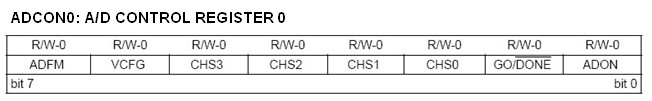
The CHS3, CHS2, CHS1 and CHS0 bits are used to select the ADC input channel, by setting all these bits to the logical “0” means we choose the channel 0 or AN0 (PIN 19) port which connected to the user’s trimport on the PICJazz 16F690 board.
VCFG is the voltage reference bit, the voltage reference is needed by the ADC peripheral circuit to do the converting. By setting this bit to “0” means we choose the Vdd (the PIC16F690 input voltage) as the voltage reference. The 10-bit ADC result is presented in both ADRESH and ADRESL register as follow:
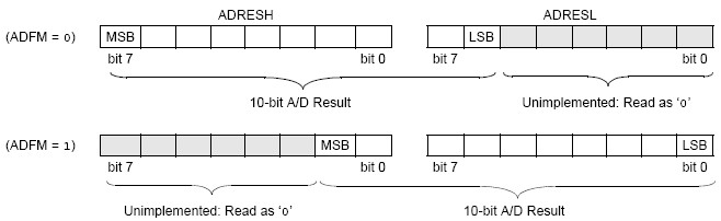
By setting the ADFM bit to logical “1” we use the “right justified” result. This mean the higher 2 bits value will be place in the ADRESH register and the lower 8 bits value are in the ADRESL register. By using the C left shifting operation, we could get this 10-bit value as this following code:
iDelay = ADRESL;           // Get the 8 bit LSB result
iDelay += (ADRESH << 8);   // Get the 2 bit MSB result
Powering the ADC circuit is simply turning on the ADON bit by setting it to logical “1” and to instruct the PIC microcontroller to start the conversion we just turn on the GO/DONE bit (logical “1“) and wait until this bit turn off when the PIC16F690 microcontroller ADC peripheral done with the conversion; we use the C while statement to wait the ADC conversion as this following code:
GODONE=1; // initiate conversion on the channel 0
while(GODONE) continue; // Wait convertion done
2. ADCON1: A/D CONTROL REGISTER 1
In order for ADC circuit inside the PIC16F690 microcontroller to work which is use the successive approximation method, it needs to be supplied with the clock for doing the conversion. This ADCON1 register is used to select the clock sources.
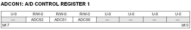
Because we are using the internal clock (FRC) of 8 Mhz, then we set these ADC clock selection bits to ADCS2 = 0, ADCS1 = 1 and ADCS0 = 1 as this following code:
ADCON1=0b00110000; // Select FRC for 8 Mhz
If you are using the external clock with VDD greater than 3 volt; make sure you choose the selection bellow typical 4us (TAD time) needed by 10-bit PIC16F690 ADC peripheral to do the conversion as this following guide (for more information please refer to the PIC16F690 datasheet):
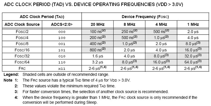
For example if you use the external clock of 4 Mhz, in order for PIC16F690 ADC peripheral to accurately converting the analog value you only have two recommended choices either choose the Fosc/8 or Fosc/16.
The PIC16F690 microcontroller ADC peripheral is also capable of generating interrupt when it finish the conversion by setting the ADC interrupt flag ADIF bit to logical “1” in PIR1 register, but for the purpose of this tutorial we will not use this facility.
The Port Initiation
One of the most important setup before we could use the ADC is to configure the PIC16F690 port as the analog input this can be done by setting the TRISA, ANSEL and ANSELH registers as the following code:
TRISC = 0x00;        // Set All on PORTC as Output
TRISA = 0x03;        // Input for RA0 and RA1
ANSEL = 0b00000001;  // Set PORT AN0 to analog input AN1 to AN7 digital I/O
ANSELH = 0;          // Set PORT AN8 to AN11 as Digital I/O
Because the PICJazz 16F690 bard use both RA0 and RA1 ports as an input ports (RA0 for user’s trimport and RA1 for user’s switch) then we turn on the tristate input gate on these ports by setting the TRISA to 0x03 and enabling the AN0 analog input selection by setting the ANSEL to 0b00000001 (0x01 hex value). For the LED’s, we just enabling all of the PORTC tristate gate ports as an output by setting the TRISCregister to all zero.
Downloading the Code
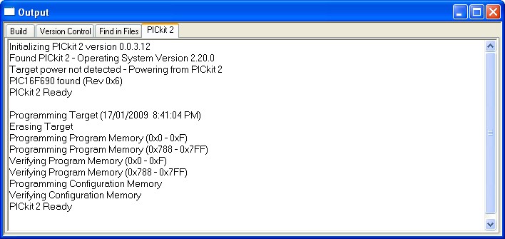
After compiling and simulating your code hook up your PICKit2 programmer to the PICJazz 16F690 board ICSP port turn the PICJazz 16F690 power. From the MPLAB IDE menu select Programmer -> Select Programmer -> Pickit2 it will automatically configure the connection and display it on the PICkit2 tab Output windows:
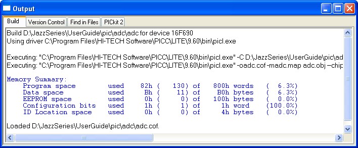
Now you are ready to down load the code from MPLAB IDE menu select Programmer -> Program; this will down load the HEX code into the PICJazz 16F690 board:
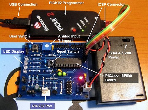
Now just relax and enjoy your work by watching your PIC 16F690 ADC in action:
Source : PIC Analog to Digital Converter C Programming
- How is the speed of the running LEDs controlled?
The speed is controlled by the voltage value read from the user trimpot on port RA0, which is converted by the ADC and passed as a delay argument. - What happens when the user switch is pressed once?
Pressing the switch toggles the display mode from running LEDs to blinking LEDs. - Which register is used to select the ADC input channel?
The ADCON0 register is used to select the ADC input channel via its CHS bits. - How is the 10-bit ADC result retrieved in the code?
The 8-bit LSB is read from ADRESL and the 2-bit MSB is shifted left and added to it to form the full value. - What clock source is selected for the ADC in this tutorial?
The internal FRC clock of 8 MHz is selected for the ADC conversion. - Which ports are configured as digital outputs for the LEDs?
All ports on PORTC are configured as outputs to drive the LEDs. - What is the function of the ANSEL register in this project?
The ANSEL register sets PORT AN0 to an analog input while keeping other ports as digital I/O. - How does the user trimpot affect the circuit operation?
The trimpot acts as a voltage divider providing a variable voltage level to the analog port AN0.