
Summary of 30th Anniversary of the Chernobyl Tragedy – or – Building a PIN Diode Geiger Counter
Exactly 30 years after Chernobyl and five after Fukushima, the author built a PIN photodiode–based Geiger counter out of curiosity and interest in fluorescent uranium minerals. The design uses two BPW34 photodiodes in parallel, two transistors for pulse amplification, and a 9 V battery to boost pulse height. Diodes were dipped in Plasti Dip for light protection; additional tin foil shielding tied to ground was also tried. Initial tests showed mostly noise and strong sensitivity to electromagnetic interference; the author is redesigning the circuit for improved results.
Parts used in the PIN Photodiode Geiger Counter:
- BPW34 photodiodes (two, Vishay)
- Transistors (two)
- 9 V battery
- Plasti Dip liquid rubber (for coating diodes)
- Tin foil (shield, connected to ground)
- Microphone input / sound card (for signal capture)
Exactly 30 years ago a great disaster struck the region of Chernobyl: a nuclear accident occurred that released a large quantity of radioactive particles into the atmosphere. And it is only five years ago that, with the Fukushima Daiichi nuclear disaster, a second similar catastrophic event has taken place.
These anniversaries did not directly let me build a PIN Photodiode based Geiger Counter, it is more or less a coincidence. The main drive to build such a device was my curiosity and (please forgive me) a fascinating green glow I’ve seen on various fluorescent Uranium minerals under UV light. But in this context it should not be forgotten that at present there still is a significant increase in background radiation in some regions and some agricultural products due to these events.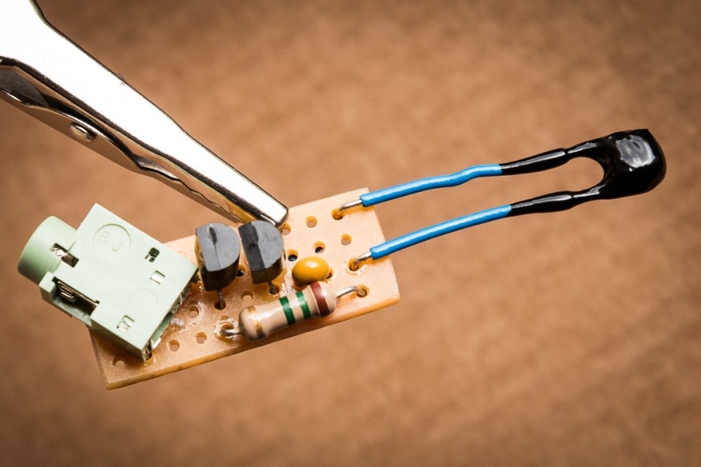
There are lots of descriptions of how to build such a device; even cheap commercial products (e.g. the Smart Geiger) use such a design. Especially two sites caught my attention: OpenGeiger.de and Das Gammastrahlen-Mikrofon (German). The design I’ve chosen is based on these sources but I’ve begun to further modify it. In this post I’m showing the design I’ve started with. It mainly relies on two BPW34 (Vishay Datasheet) photodiodes connected in parallel, and two transistors to amplify the voltage fluctuations of beta and/or gamma rays striking the diodes. A 9 Volt battery was added to increase the pulse height.
The common approach to protect the photodiodes from light is to use one layer of tin foil and connect it to ground. This should also protect the circuit against electromagnetic radiation. I’ve started with something different and dipped the diodes three times into liquid rubber (Plasti Dip). My hope was to at least allow some beta particles to reach the semiconductor material.
So far I’ve tested the basic design shown above and had mostly noise on my microphone input. I’d say that sporadic crackling has more to do with the 1 hour hacked together design than beta or gamma rays. The liquid rubber seems to block of light, but the simple design is sensitive to electromagnetic radiation. Waving your hand or even movements in about 1 m distance is visible in the sound profile. An additional tin foil shield connected to ground did not change the noise profile, although the EMR influence was reduced. I’ve tested it with two different sound cards (microphone inputs).
I’m currently redesigning the whole approach and expect better results. So stay tuned…
For more detail: 30th Anniversary of the Chernobyl Tragedy – or – Building a PIN Diode Geiger Counter
- What photodiodes were used in the project?
The project used two BPW34 photodiodes (Vishay). - How were the photodiodes protected from light?
The diodes were dipped three times into Plasti Dip liquid rubber and additionally tin foil was used as a shield connected to ground. - Does the design include amplification?
Yes, the design uses two transistors to amplify voltage fluctuations from radiation strikes on the diodes. - What power source was added to increase pulse height?
A 9 V battery was added to increase the pulse height. - How was the signal captured for testing?
The output was monitored through a microphone input on a sound card. - Did the initial tests detect radiation effectively?
Initial tests produced mostly noise and sporadic crackling, likely due to the quick prototype rather than clear radiation signals. - Was the device sensitive to electromagnetic interference?
Yes, the simple design was sensitive to electromagnetic radiation; movements about 1 m away affected the sound profile. - Did adding a tin foil shield improve noise performance?
Adding a tin foil shield connected to ground reduced EMR influence but did not change the overall noise profile. - Are further improvements planned?
Yes, the author is redesigning the whole approach and expects better results.

