
Summary of Pic 16F676 ICSP programing socket for the PICkit 2 programer
This article details a quick, space-saving method to create an ICSP socket for a PIC16F676 microcontroller using an 18-pin DIL socket and an experiment board with 2.54mm holes. The design connects specific pins to accommodate the PICkit 2 programmer without requiring custom PCB manufacturing.
Parts used in the PIC 16F676 ICSP programming socket:
- Experiment board with raster 2.54mm holes
- 18pin DIL IC socket
- PIC16F676 microchip (14-pin)
- 5pins angled pin header
- AWG26 PTFE red wire
- AWG26 PTFE yellow wire
I’m trying to build this dual DC motor module for my robot project
And I did not have the space for placing an ICSP pin header on the PCB.
So i quickly mocked up this design.
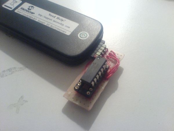
Step 1: Geting the parts
Well to build the ICSP socket with header for the PICkit 2. We need 1part experiment board I used the one with raster 2.54mm holes where every 3 are connected in rows of solder islands.
I had one 18pin DIL IC socket just lying around so i used that one. (the 16F676 is a 14pin chip)
and i took 5pins angled pin header (Always have lots of break of pin headers at home.)
and some AWG26 PTFE red and yellow wire.
Step 2: Drawing
Well this is pretty straight forward just draw out your design on the experiment PCB
Just follow this table, for the 16f676.. I have not checked it up but this may be the same for all 14pin pic16F***
ICSP connector function pic pin
1 MCLR/VPP 4
2 VDD 1
3 VSS 14
4 ICSPDAT 13
5 ICSPCLK 12
For more detail: Pic 16F676 ICSP programing socket for the PICkit 2 programer
- What problem does this project solve?
The design solves the lack of space for placing an ICSP pin header on a PCB by mocking up a quick solution. - How do I connect the MCLR/VPP pin?
The MCLR/VPP function connects to pin 4 of the 16F676 chip via pin 1 of the ICSP connector. - Which pin header type is recommended?
A 5pins angled pin header is used in this build. - What type of experiment board should be used?
An experiment board with raster 2.54mm holes where every 3 are connected in rows of solder islands is required. - Can this design work for other PIC chips?
The author suggests it may be the same for all 14pin pic16F*** chips but has not verified it. - What wire gauge is used for connections?
AWG26 PTFE red and yellow wire is used for the wiring. - Why was an 18pin DIL socket chosen?
An 18pin DIL IC socket was used because the author had one lying around, even though the chip is only 14 pins. - What tool is this socket designed for?
The socket is designed for use with the PICkit 2 programmer.
