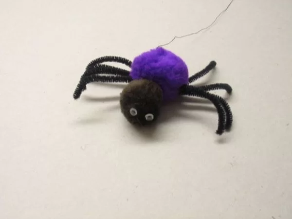
So Max the spider visited us in the lab today, and wanted to get into the halloween spirit. “I’d like to drop down on people in the elevator,” he smirked, in a way only a spider could.
“I’ve got just the thing,” I winked, and put a little something together. You’re looking at a clear Lego motor (comes with its own gearbox), mounted on a Lego platform. The platform is not going to win any design awards, but it is stable and holds the motor, circuit board and 3 AAA batteries pretty well.
I tied a thread to max, and hoisted him on the plastic winch. When I press a button on any regular remote control, he descends on hapless victims with relish. Tee hee.
Video: nwanua.aniomagic.com/max-the-spider.mov
Step 1: Circuit board
The circuit board contains:
– PIC 12f675 microcontroller
– PNA4602M infrared detector
– 2 IRL9530N power MOSFETs (P-channel)
– 2 IRL520N power MOSFETs (N-channel)
– 100uF capacitor
– five 1n914 diodes
– 3 AAA batteries
The whole thing is probably over-designed, and the transistors are overkill, but this is what I could grab and put together in 30 minutes. If the inputs to the H-bridge (four transistors) are different, your motor will turn (eg. 0,1 to turn CW, and 1,0 to turn CCW). If the inputs are the same ( 0,0 or 1,1) the motor is shorted and it stops very quickly. Don’t leave out the diodes, as they prevent the motor from spiking energy back into the transistors.
For more detail: Max the Spider – powered by LEGO and PIC microcontroller

