Summary of Build a Programmer for the 68HC705C8 MicroController
This article describes a simple programmer circuit for Motorola 68HC705C8 (or C8A) microcontrollers, detailing hardware, interfaces, power, construction, and testing. It explains use of a MAX233 for RS232-level serial, a LM78L05 regulator for 5 V, a 15.5 V programming supply, LEDs for status, PCB assembly recommendations, resistor types, and initial power-up voltage checks.
Parts used in the 68HC705C8 Programmer:
- Motorola 68HC705C8 (or C8A) microcontroller (U1)
- MAX233 serial interface driver
- LM78L05 voltage regulator (U3)
- Connector P1 (power input)
- Connector P2 (programming voltage input)
- Electrolytic capacitors (including C5)
- Other capacitors (decoupling and bypass)
- Resistors: 470 ohm, 2.7K ohm, 10K ohm, 10M ohm (including SIP resistor)
- LED indicators (two LEDs)
- IC sockets
- Printed circuit board or prototype PCB (Radio Shack 276-168B)
- Soldering materials and wiring for point-to-point construction
Introduction
This programmer is used for programming the Motorola 68HC705C8 (or C8A).
The 68HC705C8 has the following attributes;
- 8K bytes of internal EPROM
- 304 bytes of internal RAM
- 24 user-definable input/output ports
- 7 Input only ports
- Serial Control Interface (SCI)
- Serial Peripheral Interface (SPI)
- 16 bit capture/compare timer system
- Watch Dog timer
 This micro-controller is used in numerous projects available from Midon Design. Programming is very straight-forward when this programmer is used in conjunction with the easy to use DOS-compatible software also available from Midon Design. Both One Time Programmable (OTP) and EPROM versions of the 68HC705C8 can be programmed with this circuit.
The PC software used to program the micro-controllers was written and developed by Gil Shultz.
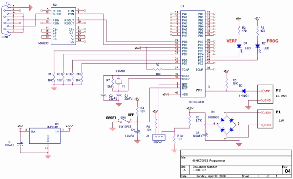
As you can see from the schematic diagram in Figure 2, this is a very simple circuit built around Motorola’s 68HC705C8 8 bit micro-controller.
The SCI is connected to a MAX233 serial interface driver from Maxim. This five-volt only device converts the TTL level serial communications to standard RS232 levels through the use of built-in voltage converters. No external capacitors or additional power supplies are required to obtain the ± 12 volts required for standard RS232 levels.
A simple power supply, consisting of U3 and C5, converts 12 volt DC to the 5 volts required for the circuit. A LM78L05 version of voltage regulator was used due to the low power consumption (less than 32mA, worst-case) of the circuit. The programming voltage, 15.5VDC ± 0.5V, is connected when requested to connector P2.
Two LED’s are available to provide a visual state of programming.
Construction
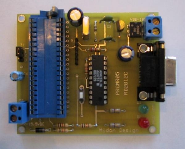
Standard construction techniques may be used for this circuit and a printed circuit board is available if desired. The prototype was point-to-point wired on a Radio Shack prototype PCB (part # 276-168B).
If building the Programmer from the PCB, refer to Figure 3 for component placement. Begin by inserting IC sockets (highly recommended). Follow this with the insertion of all passive components. I like to proceed by inserting all resistors, then all capacitors. Watch the polarity of the electrolytic capacitors. The positive lead of the electrolytic capacitors is the square pad for that component.
 There are only 4 types of discrete resistors; 470, 10K, 2.7K and 10M. The color codes for these are shown in Table 1. Insert the resistors where shown in Figure 3. The SIP resistor should be mounted as shown, with care to ensure pin 1 is oriented to the square pad on the PCB.
Next, insert voltage regulator U3. At this time, you should also insert connectors P1 and P2. Once that is done, put down the soldering iron and get out a suitable power supply. Connect the power supply to the terminals of P1, being careful to connect the proper polarity to the correct terminal. Power up and then measure voltages between pins 40 and 20 of IC U1. Pin 40 should be +5 volts while pin 20 is ground. If you are wiring this circuit on your own board, then check polarity on the other IC socket as well. Table 2 shows the voltages required on each IC.
For more detail: Build a Programmer for the 68HC705C8 MicroController
- What microcontroller does this programmer support?
The programmer is used for the Motorola 68HC705C8 (or C8A) microcontroller. - Can both OTP and EPROM versions be programmed?
Yes. Both One Time Programmable and EPROM versions of the 68HC705C8 can be programmed with this circuit. - How is serial communication achieved with a PC?
The SCI is connected to a MAX233 serial interface driver which converts TTL serial to RS232 levels internally. - Does the MAX233 require external capacitors or supplies?
No. The MAX233 provides the required RS232 voltages without external capacitors or additional power supplies. - What power supplies are required for the programmer?
The circuit requires a 12 V DC input (to P1) and a programming voltage of 15.5 VDC ± 0.5 V connected to P2 when requested; U3 (LM78L05) provides +5 V for the circuit. - Which voltage regulator is used and why?
A LM78L05 voltage regulator is used due to the low power consumption of the circuit (less than 32 mA worst-case). - What visual indicators are provided?
Two LEDs are available to provide a visual state of programming. - What construction methods are recommended?
Standard construction techniques may be used; a PCB is available, but point-to-point wiring on a prototype PCB was used for the prototype. - What initial power-up checks are suggested?
After applying power to P1, measure voltages between pins 40 and 20 of IC U1: pin 40 should be +5 V and pin 20 should be ground; check other IC socket polarities as listed in Table 2. - Who wrote the PC programming software?
The PC software used to program the microcontrollers was written and developed by Gil Shultz.