Summary of Photo film processor
This article details the electronic control unit for a homemade film processing machine. The system automates temperature control, agitation, and timing using a Basic Stamp 2p microcontroller. It features a 16x2 LCD display, pushbutton input, and a digital temperature sensor (DS18S20). Temperature is regulated via a TRIAC and heater, while rotation is managed by two independent 555 timer chips. A backup battery ensures operation during power outages, and a serial port allows software updates from a PC.
Parts used in the Homemade Film Processing Machine:
- Basic Stamp 2p microcontroller
- 16x2 character alphanumeric backlit LCD
- Two pushbuttons
- Small speaker
- Dallas DS18S20 digital temperature sensor
- Insulated-tab TRIAC
- 2000 Watt heater
- Two 555 timer chips
- Adjustable voltage regulator
- Rotation motor
- Auxiliary 12V battery input
- Two DIN connectors
- DB-9 serial port
- Standard wall outlets for line voltage outputs
On this page you will find the technical information for building the electronic control unit of my homemade film processing machine. To see the rest of this film developing apparatus, look at the relevant article in the photography section of this site.
Developing a color film is a simple procedure of putting it in a sequence of several chemical baths, for reasonably precise times at reasonably precise temperatures and with sufficient agitation. It can be done by hand, but when one has to develop films pretty often, that soon gets old! And there is another large advantage to a processing machine: Consistency. With a machine, the process will be exactly the same every time, so there are no nasty surprises with under- or overdeveloped films, color shifts, and the like.
 This machine essentially does three things: It controls the process temperature, provides constant agitation of the chemical baths, and performs the timing. The operator must pour in and out the liquids by hand.
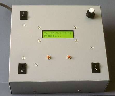
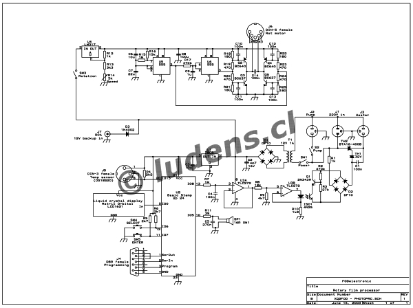
The heart of the circuit is a Basic Stamp 2p microcontroller. It has a program loaded that contains several film processing algorithms. For each of them, the process temperature, the bath sequence, the bath names, and durations, are stored. The program offers the options via a menu, displayed on a 16×2 character alphanumeric backlit LCD, while user input is through two pushbuttons. A small speaker gives confirmation beeps, and is also used to signal the end of the process time for each bath.
The processor reads a Dallas DS18S20 digital temperature sensor, which is immersed in the water bath, and uses this information to display the temperature on the LCD, and to control the phase angle of conduction for the heater. For this purpose, a proportional-integral control characteristic is implemented in software. This routine generates an analog output value, which is output on a digital pin through pulse width modulation, and used in an extremely simple but effective optocoupled phase control circuit. The power device is an insulated-tab TRIAC which can be mounted directly to the metal box of the processor. This TRIAC can easily control de machine’s 2000 Watt heater.
Rotation control is implemented completely separate from the microprocessor. 555 chips are so cheap that it’s not worth the effort to put the rotation control routine into the Basic Stamp, which would generate some difficulties with precise timekeeping, since the Stamp has no realtime multitasking. And anyway the power and interface circuit would be necessary. So I used two 555 timers, connected in such a fashion that the rotation motor runs 30 seconds to one side, then stops for one second, runs 30 seconds to the other side, stops, and so on. To control the rotation speed, the entire “reversomatic” circuit is powered from an adjustable voltage regulator. This IC must be mounted with insulation, as its tab is connected to the internal circuit. A simple switch is used to enable or disable rotation.
The power supply for the electronics is totally conventional. There isn’t much to say about it, except that an auxiliary 12V input is provided. You can connect any 12V battery here. During normal operation, the internal voltage is higher and the battery will just sit there, but in the event of a power failure the battery keeps the electronics running, thus saving your film from suspended processing! Depending on the likelihood of power failures in your area, this can be an important feature. The heater of course stops working when the power fails, but given the large thermal mass of the 30 liters of water used in this processor, the temperature holds stable enough to complete processing without severe degradation.
Two DIN connectors are used for the rotator deck and the temperature sensor. They are wired in such a way that accidental connection of the wrong device to an outlet will not cause any damage. Actually, it would be perfectly possible to use a single 5-pin connector for both the motor and the sensor. If you don’t mind having the two units bound together by a sort of umbilical cord, you can do that.
 The line voltage outputs to the heater and circulation pump use standard wall outlets. For line power input, you can use a directly connected cable, or some kind of appropriate input connector. Make sure it’s beefy enough to handle the 2kW power of the heater! Many connectors made for electronic equipment are not.
There is also a DB-9 serial port. This is directly connected to a PC serial port. Using the software provided for free on the Parallax web site, you can load the software for the Basic Stamp without even opening the box. This is convenient specially to quickly add algorithms for new film processes you may want to run, or to tweak the parameters for some special kind of process.
For more detail: Photo film processor
- What are the three main functions of this machine?
The machine controls process temperature, provides constant agitation of chemical baths, and performs timing. - How does the microcontroller manage temperature control?
The processor reads a Dallas DS18S20 sensor and uses proportional-integral control in software to adjust the TRIAC phase angle via pulse width modulation. - Why were 555 timers used instead of the microprocessor for rotation?
The author chose 555 timers because they are cheap and avoid precise timekeeping difficulties associated with the Stamp's lack of real-time multitasking. - Can the machine operate if the main power fails?
Yes, an auxiliary 12V battery keeps the electronics running during power failures to prevent suspended processing. - How can new film processing algorithms be added?
You can load new software via the DB-9 serial port connected to a PC using free software from the Parallax website. - What type of connector is used for the rotator deck and temperature sensor?
Two DIN connectors are used to prevent accidental damage from incorrect device connections. - Does the heater stop working during a power failure?
Yes, the heater stops when power fails, but the large thermal mass of the water maintains a stable temperature long enough to finish processing. - What is the maximum power the heater consumes?
The heater consumes 2000 Watts of power.