A circuit breaker is an automatically operated electrical switch designed to protect an electrical circuit from damage caused by overload or short circuit. Its basic function is to detect a fault condition and interrupt current flow. Unlike a fuse, which operates once and then must be replaced, a circuit breaker can be reset (either manually or automatically) to resume normal operation.

When operated manually we see fatal electrical accidents to the line man are increasing during the electric line repair due to the lack of communication and coordination between the maintenance staff and the electric substation staff. In order to avoid such accidents, the breaker can be so designed such that only authorized person can operate it with a password. Here, there is also a provision of changing the password. The system is fully controlled by the 8 bit microcontroller of 16f877A family. The password is stored in an EEPROM, interfaced to the microcontroller and the password can be changed any time unlike a fixed one burnt permanently on to the microcontroller. A keypad is used to enter the password and a relay to open or close circuit breaker, which is indicated by a lamp. Any wrong attempt to open the breaker (by entering the wrong password) an alert will be actuated, indicated by another lamp. Index terms: Resistors, Capacitors, Diodes, Transistors, Voltage regulator, Rectifier, Microcontroller, EEPROM, Relay, Relay Driver
Step 1: Introduction:
Nowadays, electrical accidents to the line man are increasing, while repairing the electrical lines due to the lack of communication between the electrical substation and maintenance staff. This project gives a solution to this problem to ensure line man safety. In this proposed system the control (ON/OFF) of the electrical lines lies with line man. This project is arranged in such a way that maintenance staff or line man has to enter the password to ON/OFF the electrical line. Now if there is any fault in electrical line then line man will switch off the power supply to the line by entering password and comfortably repair the electrical line, and after coming to the substation line man switch on the supply to the particular line by entering the password
Step 2: Key Features:
In this project we are easily break the load by keypad.
• This proposed system provides a solution, which can ensure the safety of the maintenance staff e.g. line man.
• This system has an arrangement such that a password is required to operate the circuit breaker (ON/OFF).
• Line man can turn off the supply and comfortably repair it, and return to the substation, then turn on the line by entering the correct password
Step 3: Making PCB on Proteus

Step 4: Study Requires and Components Description
Study Required:
• Interfacing of PIC microcontroller
• Interfacing of LCD
• Interfacing of Relays
• Interfacing of Keypad
• MicroC
• Proteus
Hardware Requirement:
• Lm7805,7812
• Capacitors
• Crystal 4MHZ
• Pic16f877A
• Relays
• Led’s
• Buzzer
• Keypad-Phone 4×3
• 16 pins LCD
• Load (Appliance)
• Pushbutton
• Resistances 330,10k,4.7k
• Connectors connecting wires
Description:
RESISTORS: A resistor is a two-terminal electronic component designed to oppose and electric current by producing a voltage drop between its terminals in proportion to the current, that is, in accordance with Ohm’s law: V = IR. Resistors are used as part of electrical networks and electronic circuits. They are extremely common place in most electronic equipment. Practical resistors can be made of various compounds and films, as well as resistance wire.
CAPACITOR: A capacitor or condenser is a passive electronic component consisting of a pair of conductors separated by a dielectric. When a voltage potential difference exists between the conductors, an electric field is present in the dielectric. This field stores energy and produces a mechanical force between the plates. The effect is greatest between wide, flat, parallel, narrowly separated conductors.
DIODES: Diodes are used to convert AC into DC these are used as half wave rectifier or full wave rectifier. When used in its most common application, for conversion of an alternating current (AC) input into a direct current (DC) output, it is known as a bridge rectifier. A bridge rectifier provides full-wave rectification from a two-wire AC input, resulting in lower cost and weight as compared to a rectifier with a 3-wire input from a transformer with a center-tapped secondary winding
TRANSISTORS: A transistor is a semiconductor device used to amplify and switch electronic signals and electric power. It is composed of semiconductor material with at least three terminals for connection to an external circuit. A voltage or current applied to one pair of the transistor’s terminals changes the current through another pair of terminals. Because the controlled (output) power can be higher than the controlling (input) power, a transistor can amplify a signal. Today, some transistors are packaged individually, but many more are found embedded in integrated circuits. The transistor is the fundamental building block of modern electronic devices, and is ubiquitous in modern electronic systems.
VOLTAGE REGULATOR: 7805 is a voltage regulator integrated circuit. It is a member of 78xx series of fixed linear voltage regulator IC’S. The voltage source in a circuit may have fl voltage output. The voltage regulator
IC maintains the output voltage at a constant value. The xx in 78xx indicates the fixed output voltage it is designed to provide. 7805 provides +5V regulated power supply. Capacitors of suitable values can be connected at input and output pins depending upon the respective voltage levels.
RECTIFIER: A rectifier is an electrical device that converts alternating current (AC), which periodically reverses direction, to direct current (DC), current that flows in only one direction, a process known as rectification.
MICROCONTROLLER: A microcontroller (sometimes abbreviated μC, uC or MUC) is a small computer on a single integrated circuit containing a processor core, memory, and programmable input/output peripherals. Program memory in the form of Ferroelectric RAM, NOR flash or OTP ROM is also often included on chip, as well as a typically small amount of RAM. Microcontrollers are designed for embedded applications, in contrast to the microprocessors used in personal computers or other general purpose applications
EEPROM: EEPROM (also written E2PROM and pronounced “e-e-prom”, “double-e prom”, “e-squared”, or simply “e-prom”) stands for Electrically Erasable Program able Read Only Memory and is a type of non-volatile memory used in computers and other electronic devices to store small amounts of data that must be saved when power is removed, e.g., calibration tables or device configuration. When larger amounts of static data are to be stored (such as in USB flash drives) a specific type of EEPROM such as flash memory is more economical than traditional EEPROM devices. EEPROMs are organized as arrays of floating gate transistors.
RELAY: A relay is an electrically operated switch. Many relays use an electromagnet to mechanically operate a switch, but other operating principles are also used, such as solid state relays. Relays are used where it is necessary to control a circuit by a low-power signal (with complete electrical isolation between control and controlled circuits), or where several circuits must be controlled by one signal. The first relays were used in long distance telegraph circuits as amplifiers: they repeated the signal coming in from one circuit and re-transmitted it on another circuit. Relays were used extensively in telephone exchanges and early computers to perform logical operations
The main component in the circuit is 16f877A microcontroller.
In this project 4×3 keypad is used to enter the password. The password which is entered is compared with the predefined password. If entered password is correct then the corresponding electrical line is turned ON or OFF. In this project a separate password is provided to each electrical line. Activation and deactivation of the line (circuit breaker) is indicated by the load.
Block Diagram:
Simulation and Working:
For the operation of circuit breaker through a password, program is written in MicroC software and created into a .hex file that is further burnt onto the controller with the help of pickit2 The programming c coding are here in the fig.
MICROCONTOLLER PIN CONFIGURATION: Microcontroller is interfaced with keypad, EEPROM, relay driver, voltage regulator and C program. Out of four ports of microcontroller pin configuration, the upper pins of port B, i.e., pin D0 to pin D3 of the microcontroller are connected to the row lines of the keypad and lower pins (D3 to D7 ) are connected to the column lines. These are connected in such a way that the column lines acts as input to the microcontroller, and the row line as output lines. The input lines are pulled up internally. Here 16×2 LCD is connected to the port b0 and port b5 pins.
Operation:
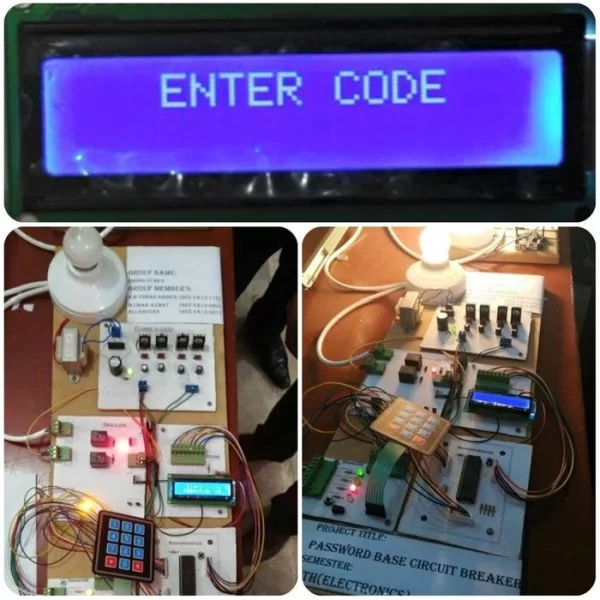
For the operation of circuit breaker through a password, program is written in MicroC software and created into a .hex file that is further burnt onto the controller with the help of pickit2. Connections are given as per the circuit diagram. While giving the connections, it should be made sure that there is no common connection between AC and DC supplies. 5V power supply circuit is to be used to provide regulated 5V DC to the controller. Now both the AC and DC supplies are switched on. Relay output pins gets 230V, so they should not be touched. LCD displays “enter password”. Enter the password with the help of keypad, you can see ‘*’ for each digit. Now if the password is correct then the circuit breaker state changes and displays status line on the LCD screen. If the password is wrong then it displays “access denied”. Since this is a user changeable one, to change the password click on ‘*’, ‘#’. It will display ‘enter password’. Here the circuit is provided with a master code that is used to access the circuit by anyone. For changing the password, this master code is to be entered. Then after entering the master code, LCD displays, ‘new password’. Now any password of will can be entered. After that it displays ‘confirm password’ i.e., the new entered password is going to be stored and the person can change the status of circuit breaker only by this new password
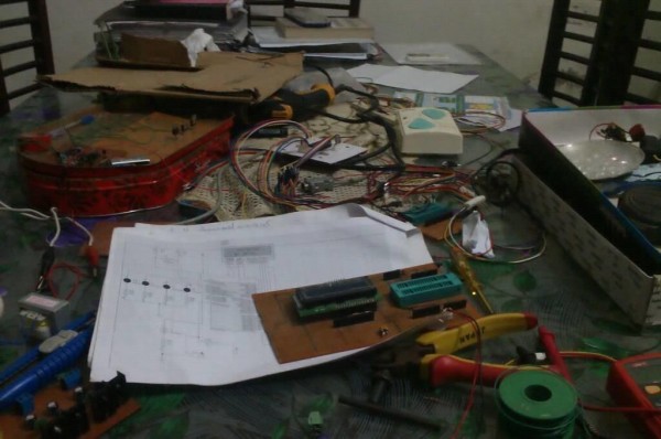
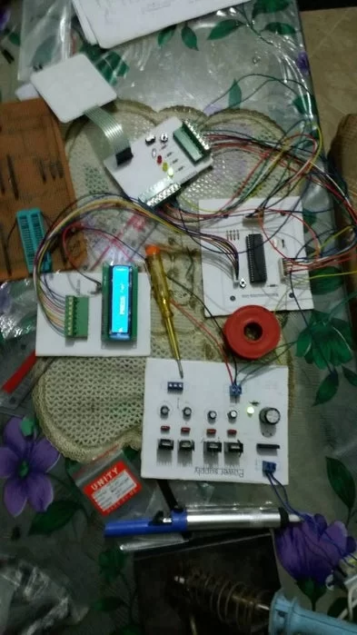
Step 5: Combine All the Units

Step 6: Final Picture