
Summary of Op-Amp Based Linear Regulators
This article explores the design and history of DIY linear regulators, contrasting them with modern monolithic ICs. It explains that while ICs are cost-effective and compact, DIY approaches using discrete components like op-amps, transistors, and voltage references can offer superior performance for specific audio applications despite requiring more board space. The text details the fundamental operation of a series linear regulator, where an error amplifier adjusts a pass transistor to maintain a stable output voltage based on a reference and voltage divider.
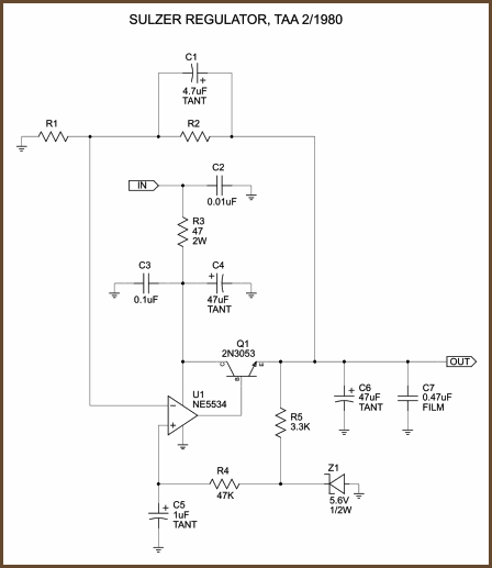
Parts used in the DIY Linear Regulator:
- Op-amp (Error Amp)
- Transistors
- Voltage Reference
- Resistors (Voltage Divider)
- NPN Transistor (Driver)
- Pass Transistor
Experienced audio DIYers are familiar with monolithic linear regulators like the 78xx series and the LM317. Here’s a simplified block diagram of a standard linear regulator, from National Semiconductor’s Application Note 1148:
Let’s see… We have an op-amp, a couple of transistors, a voltage reference, and a few resistors. Can we build a linear regulator from these individual components? Yes, we can!
Why DIY a Regulator?
Before monolithic IC regulators became popular, people made linear regulators from discrete components and maybe a general-purpose IC or two. I’ll call them DIY regulators, lacking a better term.
Like the μA741 IC op-amp did to small discrete amplifiers in the late 1960’s, the invention of the 3-terminal fixed IC regulator a few years later started pushing out DIY regulators and fully discrete regulators. These IC regulators are easy to apply, take up little board space, and have quite good performance. The secondary effects of these facts are that 3-terminal regulators like the LM317 are made by several manufacturers, and you can get them for as little as about 50 cents in single quantities. And if you want to spend a little bit of money to get even better performance, there are many improved regulators on the market. So why would one want to return to the days where people made their own linear regulators from generic parts?
The main problem with the improved IC linear regulators on the market is that they have nonstandard pinouts and they can be fairly expensive. Consider the Linear Technology LT1581 high-current high-speed LDO regulator: it’s a 7-pin TO-220 type package and it costs about $13 for single units. For $13, you can buy a pretty good collection of parts. If you can afford the board space the DIY approach takes up, you can often equal or better the performance of monolithic IC regulators.
This article follows the history of a popular series of DIY linear regulators. Starting from initial concepts basically identical to the archetype block diagram above, this particular thread through history will wind up in a very sophisticated design. Because this final design developed piecemeal over the course of two decades, that’s how I’ll show it. I think showing the steps this series of designs went through aids understanding of the final design.
We will follow the thread through the pages of the journal The Audio Amateur, the forerunner of audioXpress. audioXpress offers a complete catalog of back issues going back to 1970, so that’s how I followed the history. (Most of the back issues are still available in printed form; a few years in the 1970s are sold out now and are only available on their 1970’s reprint CD.) My purpose here is not to duplicate this material, but to summarize it and serve as a guide to it. If you want the full details of these designs, I recommend that you get the issues I reference. Many of these articles have a lot of information in them that I am glossing over here.
How Does a Series Linear Regulator Work?
The archetype block diagram above is called a series linear regulator, because the pass transistor is in series between the input and output. This type of regulator is based on a simple idea: you can control the voltage at the output leg of the transistor by manipulating the voltage at the base. Let’s study the archetype design above.
Connected to one input of the op-amp (called the error amp) is the voltage reference, VREF. You can make voltage references in many different ways, so the technology used isn’t important at this point. A good reference puts out a fixed voltage under varying conditions, and you can get versions that put out any of several standard voltages.
Connected to the other input of the error amp is the midpoint of a voltage divider. We’ll come back to this later.
An op-amp tries to make its two input voltages equal by adjusting its output voltage. In the diagram, the output of the error amp is connected to the base of an NPN transistor: when the error amp drives current into this transistor’s base, it allows current to flow from collector to emitter, and that transistor in turn pulls current from the base of the pass transistor. This arrangement lets an op-amp capable of driving a few tens of milliamps control an amp or so of current across the pass transistor.
Now comes the neat bit. Let’s say you have a 5V reference and the voltage divider is set up to divide the voltage from VOUT to GND by 4. Since the op-amp tries to make its two inputs equal and one input (the voltage reference) stays constant, it will adjust its output voltage until 5V appears at the midpoint of the divider. Since it’s a divide-by-4 voltage divider, VOUT goes to 20V and it stays there because it’s a real-time system, constantly adjusting to changing conditions.
Voilá, you have a series linear regulator.
(If you want to read more about the operation of linear regulators, I recommend reading the AN-1148 app note I reference above.)
Now, this simple design isn’t perfect. The error amp can only slew so fast, the voltage reference will have some error, the output of the regulator has an effective impedance resulting in current-modulated voltage drops, and all of the components in question will drift to some extent as the temperature changes. Furthermore, all of the components in the regulator generate some noise, and this gets worse as temperature rises.
For more detail: Op-Amp Based Linear Regulators
- Why would one want to build a DIY linear regulator?
Monolithic IC regulators often have nonstandard pinouts and can be expensive, whereas DIY designs can equal or better their performance if board space allows. - How does a series linear regulator control output voltage?
It controls the voltage at the output leg of the transistor by manipulating the voltage at its base via an error amplifier. - What is the role of the voltage divider in this circuit?
The voltage divider provides feedback to the error amp; the op-amp adjusts until the divider midpoint matches the fixed voltage reference. - Can you make a voltage reference yourself?
Yes, voltage references can be made in many different ways, and the specific technology used is not critical for the basic concept. - What limits the performance of the simple archetype design?
Limits include the error amp slew rate, voltage reference error, effective impedance causing current-modulated drops, component drift with temperature, and noise generation. - How much current can a standard op-amp drive in this configuration?
An op-amp capable of driving a few tens of milliamps can control an amp or so of current across the pass transistor. - Where did the history of these popular DIY regulator designs originate?
The history follows the pages of the journal The Audio Amateur, which is the forerunner of audioXpress.
