Summary of MRNet — Wired Cab Module (Revision A) using pic microcontroller
This article details the design of a lightweight, handheld train cab controller using off-the-shelf parts and no surface-mount chips. It outlines goals like low power consumption and customizability, specifying features such as dual 4-digit displays, LEDs, buttons, and analog inputs. The electronics rely on a Microchip PIC16C73 microcontroller managing data via shift registers, with power supplied by a rechargeable 9V battery or external source through a regulated interface.
Parts used in the Handheld Cab:
- N1 Connector (Power and Cable Interface)
- SW1 Switch
- VR1 Voltage Regulator
- C1 and C2 Capacitors
- D5 Diode and R94 Resistor
- 9-volt Nickel Cadnium Battery
- D6 Diode
- U19A Schmidt Trigger
- Microchip PIC16C73 Microcontroller
- Shift Registers (74HC164 and 74HC165)
- Four digit 7-segment LED Displays
- Individual LED's
- Buttons
- Linear Potentiometers
Table of Contents
- Table of Contents
- Introduction
- Cab Design Goals
- Cab Electronics
- Cab Printed Circuit Board
- Cab Software
- Summary
Introduction
{Introduction goes here.}
Cab Design Goals
The goals for the handheld cab are:
- Light weight.
- Comfortable.
- Not visibly warm (i.e. low power consumption).
- Assembled from readily available parts, including box.
- Customizable control labels.
- No surface mount chips.
The feature set I decided on for this handheld cab is:
- Up to two 4 digit 7-segment LED displays.
- Up to 16 LED’s.
- Up to 8 buttons.
- Up to 4 analog inputs via linear potentiometers.
Cab Electronics
The handheld cab schematics are broken into several pages. The schematics are:
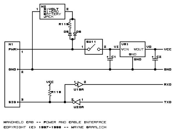
Power And Cable Interface
The first schematic shows the power and cable interface electronics:
This circuit starts with the power and ground coming on the PWR1 and GND pins of N1 and being routed through SW1 into voltage regulator VR1 with capacitors C1 and C2 to provided regulated 5 volts for the rest of the handheld cab. In addition, D5 and R94 provide a current limited supply to charge the 9-volt Nickel Cadnium battery. The 9-volt battery is chosen because it is lighter than 4 or 5 AA batteries. If the power from PWR1 and GND2 ever goes away, diode D6 will kick in and supply voltage and current for VR1 and its two capacitors C1 and C2. The concept is that the Nickel Cadnium battery is always being charged when the cab is plugged into the cab station and the battery is discharging only when the operator is moving between cabs. The on/off switch is after the battery so that the cab can be charged overnight without having to leave the rest of the electronics on. Going back to connector N1, the signal comes in on the SIG pin of N1 and is fed into the Schmidt triggerU19A and the resulting signal is fed into the UART input pin of the microcontroller. The UART output pin of the microcontroller is fed into the open collector NAND gate U19A which is pulled up by resistor R95 and the resulting output signal is sent out on the SIG pin of R95.
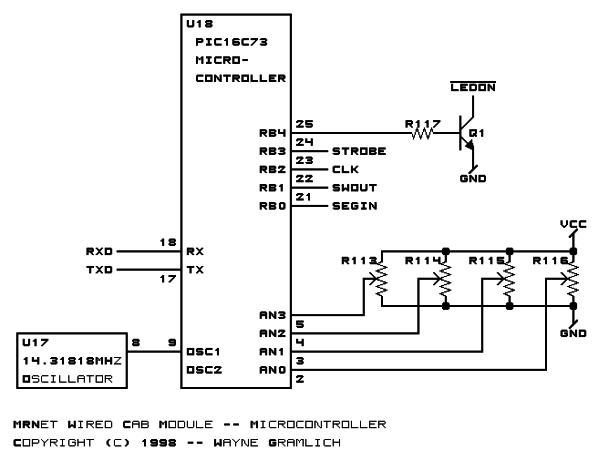
Microcontroller
The handheld cab is organized around a Microchip PIC16C73 in an 28-pin SDIP package. The PIC16C73 has a 5 channel analog to digital converter, a built in asynchronous serial port, and enough I/O pins to control the rest of the handheld cab.
Given that there are a total of 64 LED segments in the seven-segment displays, 24 indvidually controllable LED’s, and 8 button inputs, there is no way to directly connect each LED and switch to an individual pin on the PIC. Instead, I have arranged all of the input and output data as one big shift register using `164 and `165 shift registers. This is basically just a simplistic I2C bus. The code to shift 8-bits of data out looks like it will take around 32 instructions. This routine will need to be called about 12 times (12 x 32 = 384,) so an update will not be visible to the operator.
The I/O lines on the PIC are labled below:
For more detail: MRNet — Wired Cab Module (Revision A)
-
What are the primary design goals for the handheld cab?
The goals include being light weight, comfortable, having low power consumption to stay cool, using readily available parts, allowing customizable labels, and avoiding surface mount chips. -
Why was a 9-volt Nickel Cadnium battery chosen over AA batteries?
The 9-volt battery was selected because it is lighter than using 4 or 5 AA batteries. -
How does the power system handle charging versus operation?
The battery charges when plugged into the station while the on/off switch keeps the rest of the electronics off, and discharges only when the operator moves between cabs. -
Which microcontroller is used in the handheld cab project?
The project uses a Microchip PIC16C73 in a 28-pin SDIP package which features an analog to digital converter and an asynchronous serial port. -
How does the system manage connecting multiple LEDs and buttons without enough pins?
The system arranges input and output data using 74HC164 and 74HC165 shift registers instead of connecting each component directly to a pin. -
What is the estimated instruction count for shifting 8 bits of data?
The code to shift 8-bits of data out takes around 32 instructions. -
What components provide the regulated 5 volts for the circuit?
The voltage regulator VR1 along with capacitors C1 and C2 provides the regulated 5 volts after routing power through SW1.