Philips invented the RC5 protocol for controlling electronic equipment such as CD players, VCR’s and audio amplifiers way back in the 1980’s. The RC5 standard has been adopted and used with great success ever since, which means it is probably the most common IR remote control format in your home today. We have recently been playing around with a PIC microcontroller based RC5 decoder programmed in C, with the purpose of testing any RC5 based remote handset you may have. The image above shows the RC5 code for a button press of ‘1’ on the CD player remote control decoded into binary and displayed on the 14 LEDS – the address data for a CD player is ’20’ hence the 10100 binary pattern on the green LEDS. The RC5 command for ‘1’ is unsurprisingly 000001 in binary as shown on the red LEDS. The two start bit LEDS (yellow) are showing 11 binary and the toggle bit is off. In the pic below the ‘1’ button has been pressed again showing the toggle bit now being set (blue LED).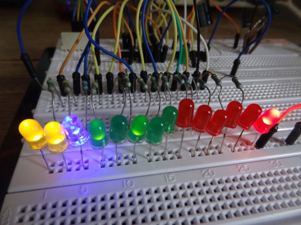
The RC5 protocol is based upon a 14 bit serial code (binary 0/1) – when a key is pressed on the remote, the following bits are emitted:-
bit 1 (start bit) S1
bit 2 (second start bit) S2
bit 3 (Toggle bit) T
bits 4 – 8 (5 device address bits) A4 A3 A2 A1 A0
bits 9 – 14 (6 command bits) C5 C4 C3 C2 C1 C0
Below is a diagram showing the 14 bit pattern and the pulse and space timings for a typical RC5 transmission. More information on RC5 including device address codes and commands can be found at the link below.
RC5 protocol
The data is encoded using Manchester or bi-phase encoding of the binary data, in order to maximise noise immunity. A logic ‘1’ is represented by a low half bit followed by a high half bit, whilst a logic ‘0’ is represented by the opposite pattern i.e a high half bit followed by a low half bit. The transition from high to low or low to high always occurs at the mid-bit point. The bit length is approximately 1778us, so the mid bit point is at 889us – in other words, each half bit is 889us long. Manchester encoded data can be decoded in one of two ways. The first method is to detect the direction of change at the mid-bit point (low to high or high to low). A high to low transition at the mid-bit point indicates a logic ‘0’ whilst a low to high transition indicates a logic ‘1’. The second method involves simply reading the logic level present in the second half of the bit period, which is the method I used for this project.
The RC5 decoding algorithm employed is written in C and is targeted at a PIC 16f690 microcontroller. A 36kHz IR receiver IC is used ( TSOP2236 but I also had good results from an old IS1U60L I had lying around) which removes the 36kHz carrier frequency from the transmitted RC5 code, leaving a binary bit stream which can be fed to the microcontroller. As the IR receivers have an active low output, I passed it’s output through a inverter (NOT) logic gate – this can also be achieved in software by reversing the logic of the code if desired. The algorithm works by first detecting the rising edge of start bit S1. S1 is not decoded as we can’t tell what happened before that first rising edge – all we know is that S1 is always logic ‘1’ so we set it to a constant ‘1’ in software. After that we get a second interrupt on change (IOC) which indicates the start of S2, which we do want to decode.The negative edge detection triggers the IOC routine again where the logic level present on RB4 (IOC input pin) is sampled after a delay of 1334us (889us x 1.5) to ensure we are 3/4 of the way though the whole bit, thereby sampling the logic level present in the second half of the bit period. In the main loop we have set up a one dimensional array of 14 elements to store the RC5 bits sequentially, incremented by index variable j. The RC5 bit pattern is then output on PORT’s A, B and C to 14 LED’s, so that the correct operation of the remote can be observed. For the prototype I made the S1 S2 bits yellow, T bit (toggle bit) blue, the device address bits green, and the command bits red. A further green LED is connected to PORTCbits.RC0 to indicate the receiving of RC5 data.
Here is the schematic – note that if you use a different IR receiver check the pin out details – they are not all the same!
RC5_schematic
One issue to be aware of is ambient light affecting the IR receiver – I found that I had to shield the receiver from ambient light using a cloth to prevent false decoding codes. Have fun !
Here is the software listing which was compiled using XC8.
/*
* File: rc5_IOC.c
* Author: Phil Glazzard
*
* Created on 07 August 2015, 20:30
*/
// PIC 16f690 Configuration bit settings
#include xc.h
// #pragma config statements should precede project file includes.
// Use project enums instead of #define for ON and OFF.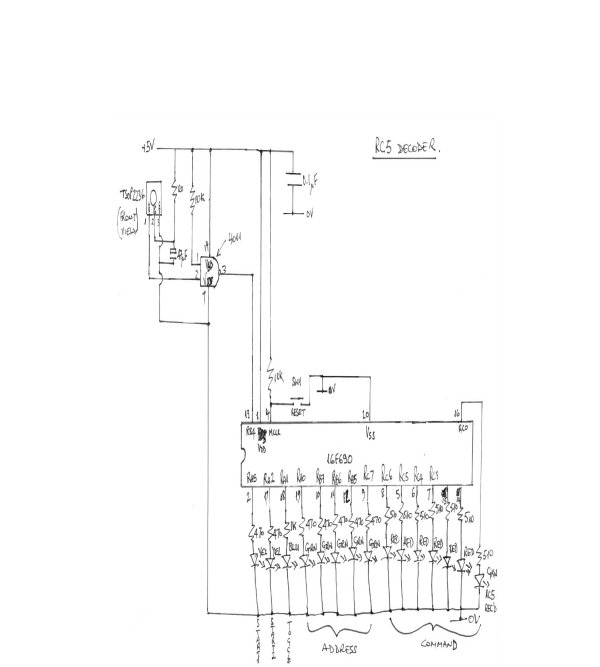
// CONFIG
#pragma config FOSC = INTRCIO // Oscillator Selection bits (INTOSCIO oscillator: I/O function on RA4/OSC2/CLKOUT pin, I/O function on RA5/OSC1/CLKIN)
#pragma config WDTE = OFF // Watchdog Timer Enable bit (WDT disabled and can be enabled by SWDTEN bit of the WDTCON register)
#pragma config PWRTE = OFF // Power-up Timer Enable bit (PWRT disabled)
#pragma config MCLRE = ON // MCLR Pin Function Select bit (MCLR pin function is MCLR)
#pragma config CP = OFF // Code Protection bit (Program memory code protection is disabled)
#pragma config CPD = OFF // Data Code Protection bit (Data memory code protection is disabled)
#pragma config BOREN = OFF // Brown-out Reset Selection bits (BOR disabled)
#pragma config IESO = OFF // Internal External Switchover bit (Internal External Switchover mode is disabled)
For more detail: Infra red remote control tester for Philips RC5 protocol