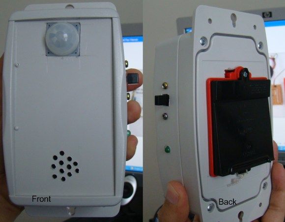
Summary of Motion detection alarm using a PIR sensor module with a PIC12F635
This project presents a motion sensor alarm using a Passive Infra-Red (PIR) sensor module and a PIC12F635 microcontroller. The PIR sensor detects infrared radiation from moving human bodies and outputs a high signal. The microcontroller monitors this output via a transistor switch to control a buzzer when motion is detected. Powered by 4 AA batteries with voltage regulation via a diode, the circuit uses internal clock oscillator for operation and allows for continuous trigger mode via a jumper setting on the PIR module. The design ensures stable operation and protection against reverse polarity.
Parts used in the Motion Sensor Alarm Project:
- PIR sensor module with Fresnel lens
- PIC12F635 microcontroller
- BC547 NPN transistor
- Buzzer
- Power supply: 4 AA batteries (6 V)
- Diode (for voltage drop and reverse polarity protection)
- Jumpers for PIR trigger mode selection
Introduction
This project describes a motion sensor alarm based on a Passive Infra-Red (PIR) sensor module. There are many vendors that manufacture the PIR sensor modules and almost all of them are pretty much the same in function. They have a single output that goes high (or low, based on specification) when the motion is detected. In this project, a PIC12F635 microcontroller continuously monitors the output from the sensor module and turns a buzzer on when it goes active.
Theory
Certain crystalline materials have the property to generate a surface electric charge when exposed to thermal infrared radiation. This phenomenon is known as pyroelectricity. The Passive Infra-Red (PIR) sensor module works on the same principle. The human body radiates heat in the form of infrared radiation which is maximum at about 9.4 um. The presence of human body creates a sudden change in the IR profile of the surrounding that is sensed by the pyroelectric sensor. The PIR sensor module has an instrumentation circuit on board that amplifies this signal to appropriate voltage level to indicate the detection of motion.
The PIR sensor requires an initial stabilization time of about 10 to 60 seconds in order to function properly. During this time, the sensor gets familiar with the surrounding environment, and any motion in its field of view should be avoided. The PIR sensor has a typical range of 20 feet, and is designed to adjust to slowly changing conditions such as the gradual change in the thermal profile of the surrounding as the day passes. However, any sudden change in the profile (e.g. human body motion) is responded by the sensor. That’s why the PIR sensor module should not be placed near a heater, AC outlet or anything that could create a rapid change in the surrounding environment.
PIR sensor modules usually have a 3-pin connection: Vcc, Output, and Ground. The pinout may vary, so I recommend to check the manufacturer’s datasheet to confirm the pins. Sometime, they do have labels on the board next to the pins. The one I have got does so, and it can be powered through 5-12 V supply as it has its own voltage regulator on board. The output goes high when the motion is sensed.
Besides it also has a 3-pin jumper selection for single or continuous trigger output mode. The two positions have labels H and L. When the jumper is at H position, the output remains high when the sensor is re-triggered repeatedly. In position L, the output goes high and low every time the sensor is triggered. So a continuous motion will give repeated high/low pulses in this mode. The front part of the sensor module has a Fresnel lens to focus the infrared light on to the sensor element.
Circuit Design and Construction
The circuit diagram is quite simple. I have powered my circuit with 4 AA batteries that gives 6 V supply. A diode is used in series to drop the voltage down to 5.4 V as the operating voltage for the PIC microcontroller should be below 5.5 V. Besides, the diode also provides the protection to the circuit in case of reverse polarity of the power supply. I have tested the circuit with NI-MH rechargeable batteries (that gives 4.8 V) and it worked, but I recommend to use the alkaline batteries (1.5 V each) for better performance. You can also use a 9 V battery but then you need a LM7805 regulator IC in your circuit.
The output of the PIR sensor module is monitored through GP5 (pin 2) of PIC12F635. When the motion is sensed, this output is high at about 3.3 V (my sensor module has a 3.3V regulator IC on board). You could still use this voltage as a valid logic high for PIC12F635, but I preferred to use this voltage to drive the base of an NPN transistor (BC547) so that at the collector we will have the full swing of the logic voltages. Now, the microcontroller monitors the voltage at the collector of the transistor. During the normal condition, the transistor is cut off, and the collector output is at logic high (+5 V). When the motion is sensed, the high output from the sensor module saturates the transistor and the voltage at the collector drops down to logic low. The jumper selection for trigger is at H position, so the sensor output will remain active as long as the motion exists. Note that the PIC12F635 microcontroller uses the internal clock oscillator at 4.0 MHz. The MCLR function is disabled and WDT is OFF in this project.
For more detail: Motion detection alarm using a PIR sensor module with a PIC12F635

