


Summary of HAPPY BIRTHDAY using PIC12F629 Microcontroller
This article describes a DIY Happy Birthday musical card project using a PIC12F629 microcontroller. It emphasizes simplicity, requiring only four components and a prototype PC board to teach programming skills. The circuit relies on a piezo diaphragm connected to specific pins, with the melody generated entirely by software. Users must burn the provided .hex file or use the .asm file for compilation.Parts used in the Happy Birthday Musical Card:
- PIC12F629 Microcontroller
- Piezo diaphragm
- Prototype PC board
- Programming cable (implied for burning the chip)
Why spend $10.00 on a Happy Birthday musical card when you can produce the tune yourself.
This project uses just 4 components and a small prototype PC board to produce a project that will teach you a lot about programming.
The circuit uses a piezo diaphragm connected to pins 3 and 5.
That's the only component.
All the work is done by the program.
The project is so easy, we don't need to provide any construction details
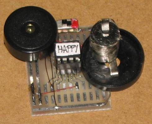
Here are the files:
HappyBirthday.asm
HappyBirthday.hex
Here is the program.
You must use the .hex file to "burn" the chip or the .asm file as these are laid out so that the compiler and programmer can understand the data.
The following program is just for viewing.
For more detail: HAPPY BIRTHDAY using PIC12F629 Microcontroller
Quick Solutions to Questions related to Happy Birthday Musical Card:
-
Why should I build this project instead of buying a card?
You can produce the tune yourself without spending $10.00 on a pre-made Happy Birthday musical card. -
How many components are required for this project?
The project uses just 4 components and a small prototype PC board. -
Which component is physically connected to the circuit?
The circuit uses a piezo diaphragm connected to pins 3 and 5. -
What generates the music in this project?
All the work is done by the program, not physical hardware beyond the diaphragm. -
Do I need construction details to build this?
No, the project is so easy that no construction details are provided. -
Which file format should I use to program the chip?
You must use the .hex file to burn the chip or the .asm file for the compiler. -
Can I view the source code directly in the article?
The program listed is just for viewing; you must download the specific files to compile or burn. -
What microcontroller is used in this design?
The project utilizes the PIC12F629 Microcontroller.
Related projects
RGB LED PWM Driver for High Power 350mA LEDs using PIC12F629
Description This project combines a PIC and three constant current 'buck' converters to produce an RGB LED controller that will operate with...
Communication & Interfacing · PIC12F629Wireless controlled lightdimmer using PIC12F629
The meaning from this design is to build it in -i.e. a shaded lamp- and to switch this lamp on and off...
LED Projects · PIC12F629Navigation Lights for Models for PIC12F629
Description This project was inspired from a post on the Picprojects forum where a member had adapted the RGB Moodlight project for...
Home Automation & SecurityVoice Activated Power Sockets (Home Automation)
Yet another voice controlled home automation system! As shown in the picture, the system can control any electrical appliance, by turning ON...
Home Automation & SecurityHome Security System with GSM Using 8051 Microcontroller
Security is a big challenge everywhere because thefts are increasing day by day owing to the unsafe and insecure security systems in...
Home Automation & SecurityHome Automation and Security System using Microcontroller ATMEGA8 with Arduino Programming
Home automation and security systems have become very popular these days, today industrial automation techniques are widely adopted by luxurious homes and...

Ibrar Ayyub
I am an experienced technical writer holding a Master's degree in computer science from BZU Multan, Pakistan University. With a background spanning various industries, particularly in home automation and engineering, I have honed my skills in crafting clear and concise content. Proficient in leveraging infographics and diagrams, I strive to simplify complex concepts for readers. My strength lies in thorough...