Summary of Mini Sumo
This article outlines the design, construction, and operation of a Sumo robot designed to push opponents out of a ring. It details necessary components like sensors, motors, and an Arduino-compatible microcontroller, along with steps for PCB assembly, chassis optimization using CAD software, coding, and Bluetooth control via a smartphone app.
Parts used in the Sumo Robot:
- PIC 16F877A
- Quartz crystal 4Mhz
- Capacitors 22pF
- Digital QTR-1RC Line Sensor
- Bluetooth mode HC-05
- Ultrasound sensor HC-SR04
- LED 3mm
- Motors 6V 0.5kg
- Bridge H TB6612
- Regulator 7805
- Capacitor 1uF
- Capacitor 0.1uF (104)
- DC-DC voltage booster
- Lithium 3.7V 3000mAh Batteries
- Battery holder for lithium battery
- Dual charger for lithium battery
- Blue terminals 3.5mm 2 positions
- header pins connectors
- Header H-H TYPE 1 connectors
- push buttons 2 pins
- Resistors 10Kohm
- 150ohm resistors
- networks
- PCB
Today we will explain how to perform the design,
operation, and construction of a sumo robot, a robot is considered an automatic programmed machine to accomplish a certain task. In this opportunity, our robot will have the task of facing another robot on the battlefield whose The aim is to move the opponent out of the field of play, for this we will explain here the step by step and the occasional key to the elaboration.
For the development of this project, it is necessary to have the following materials:
Supplies
- 1 PIC 16F877A
- 2 Quartz crystal 4Mhz
- 4 Capacitors 22pF
- 2 Digital QTR-1RC Line Sensor
- 1 Bluetooth mode HC-05
- 1 Ultrasound sensor HC-SR04
- 2 LED 3mm
- 2 Motors 6V 0.5kg
- 1 Bridge H TB6612
- 1 Regulator 7805
- 1 Capacitor 1uF
- 1 Capacitor 0.1uF (104)
- 1 DC-DC voltage booster
- 2 Lithium 3.7V 3000mAh Batteries
- 2 Battery holder for lithium battery
- Dual charger for lithium battery
- 3 Blue terminals 3.5mm 2 positions
- 2 header pins connectors
- 2 Header H-H TYPE 1 connectors
- 2 Header H-H TYPE 1 connectors
- 3 push buttons 2 pins
- 3 Resistors 10Kohm
- 2 150ohm resistors
- 2 networks (own choice)
- 1 PCB
Step 1: PCB
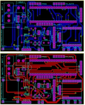
For the elaboration of our robot we will need a PCB
this is the one in charge of connecting each one of the components for optimal functioning of the circuit; This PCB is designed and ordered to be made specifically for this sumo robot model. This PCB is designed with a double layer which means that we have to weld both sides to connect the two tracks through holes that connect the two sides, these are called True holds.
Step 2: COMPONENTS
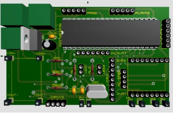
We proceed to place each of our components in the
corresponding areas as shown in the following image
The first thing we must do is solder our Truholds points, we must be very careful when welding each of the components as it is possible to lift the tracks of the PCB.
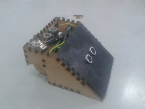
Step 3: CHASIS
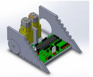
For the design of our chassis, we can use AutoCAD or
any other design program, here we will look for ways to optimize space since our robot must meet a set weight, the lighter the better the chances of winning.
Step 4: CODE
In order to give life to our beloved robot, the last
thing we have to do is take a hot glass of coffee to sit and think and program your sumo, but since you are here reading this tutorial, we have good news here you will find the code ready for you to enter in action with your robot and be the best.
Attachments
Step 5: CONTROL
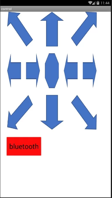
To manipulate our little friend we will resort to a
wireless control controlled by Bluetooth from the comfort of your Smartphone, in the following link that I will leave you next you will be able to see the step by step to create your personalized remote control as you want.
Source: Mini Sumo
- What is the primary aim of the sumo robot described?
The aim is to move the opponent out of the field of play. - How is the robot controlled wirelessly?
It is controlled by Bluetooth from a Smartphone. - What software can be used to design the chassis?
You can use AutoCAD or any other design program. - Why should the robot be lightweight?
The lighter it is, the better the chances of winning due to weight constraints. - Does the PCB require soldering on both sides?
Yes, it is a double-layer board requiring welding on both sides through True holds. - Can I find the code ready for the robot?
Yes, the article states that ready code is available for download as SUMO.txt. - What type of batteries are recommended?
Two Lithium 3.7V 3000mAh Batteries are listed as supplies. - Which sensor detects lines or edges?
The Digital QTR-1RC Line Sensor is used for this purpose.