Summary of Microcontroller Schematic Design Software
This article introduces Microcontroller Schematic Design Software, an Electronic Design System (EDS) for prototyping and simulating embedded systems. It outlines the design workflow from schematic creation to PCB implementation and testing. Using Proteus as a primary example, the text details its three editors: Schematic, PCB, and Programming. It describes how components like microcontrollers, voltage regulators, LEDs, power supplies, signal generators, and graph panels are utilized within the software to simulate real-time behavior for applications ranging from simple displays to complex robotics.
Parts used in the Microcontroller Schematic Design Software Project:
- Schematic Editor
- PCB Editor
- Programming Editor
- Microcontroller Library
- PIC16F84A microcontroller
- 7805 voltage regulator
- LEDs
- Active component panel
- Signal generator
- Graph panels
- Power supply terminals
- Ground terminals
- USB programming device
- Oscilloscope
- Signal generators
Microcontroller Schematic Design Software
Microcontroller Schematic Design Software is a electronics design software(EDS) that is used for the prototyping and simulation of embedded system that contains microcontrollers.
The usual steps taken for designing microcontroller based embedded system using microcontroller circuit design software are-
1. Create a schematic of the design
2. Create Program for the microcontroller
3. Upload the program to the microcontroller
4. Stimulate the design
5. Fix errors and restimulate
6. Create PCB and implement the physical design
7. Burn the microcontroller using for example USB programming device
8. Check the final design using the signals generators and oscilloscope 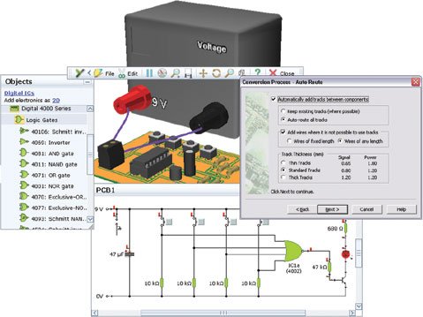
An example is Proteus(see download Proteus 8 Microcontroller Simulation Software blogpost) and how to use such microcontroller schematic design software is explained. With Proteus, microcontrollers can be drawn into the schematic editor and external circuitry around it can be drawn by wiring the components to the microcontroller and stimulated to see how the microcontroller behaves in real time. The external circuit depends upon the application for which the microcontroller is used. Controlling LEDs and LCD for display are simple examples but is not limited to this. Complex automation design such as robotic design uses microcontroller and this is where schematic design software really sparks. An example would be the control of motors and wheels of a toy car or automatic control of temperature within a room.
It has the following editors-
1. Schematic Editor
2. PCB Editor
3. Programming Editor
During the Project creation, the project wizard ask what kind of project it is whether it is schematic design only, PCB design only or Firmware programming only or a complete project that requires all of these.
Schematic with Microcontroller
An example of microcontroller schematic drawing software(Proteus) interface is shown below-
The above picture contains the PIC16F8A microcontroller which will be programmed and stimulated.
The schematic of microcontroller with external circuit is shown below-
This is a simple illustration of how the schematic design software is used for simulation of microcontroller. In the above diagram, PIC16F84A microcontroller is used and it connection to the external circuit is also shown. The external circuit consist of driving power supply regulated by the 7805 voltage regulator and LEDs are connected at the output ports. The LEDs in the schematic can be controlled using the microcontroller.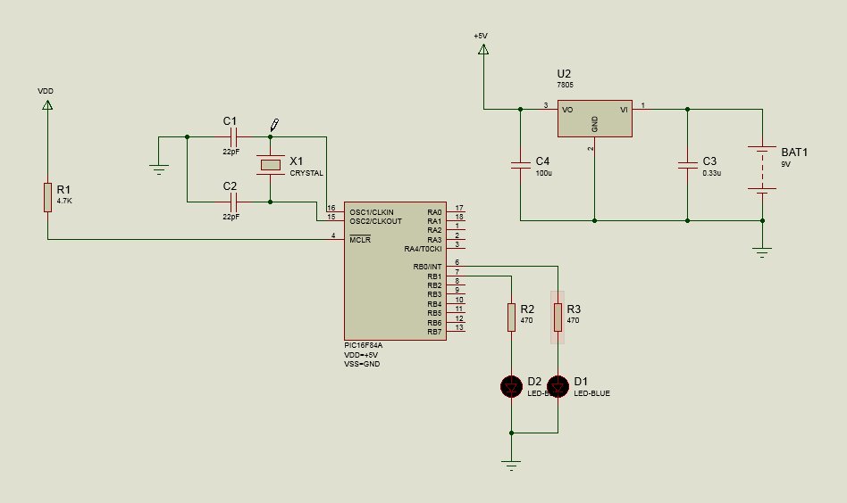
In the schematic editor, the components along with the microcontroller(s) are placed and connected together with electrical wires. Below pictures shows the active component panel, the signal generator, the graph panels for viewing the outputs, power supply and ground terminals
Power supply and Ground terminal panel-
The Output graph terminal panel-
The Signal Generator Panel-
The PCB design editor is for creating printed circuit board for the designed system and is not discussed here. The programming editor is for programming the microcontroller and will be explained below. But before programming the microcontroller firmware is explained the library of microcontroller is described.
Microcontroller Library
A microcontroller based schematic design software should have support simulation of large number ofr microcontrollers from different vendors. As an example the proeteus microcontroller library is shown below-
Source : Microcontroller Schematic Design Software
- What is Microcontroller Schematic Design Software?
It is an electronics design software used for the prototyping and simulation of embedded systems that contain microcontrollers. - How do you design a microcontroller based embedded system using this software?
The usual steps include creating a schematic, writing a program, uploading it, stimulating the design, fixing errors, creating a PCB, burning the microcontroller, and checking the final design. - Which software is cited as an example of microcontroller schematic design
software?
Proteus 8 is provided as an example of such software where microcontrollers can be drawn into the schematic editor. - What types of projects can be created using the project wizard?
The wizard allows users to select schematic design only, PCB design only, firmware programming only, or a complete project requiring all these elements. - Does the software support microcontrollers from different vendors?
Yes, a microcontroller based schematic design software should have support for the simulation of a large number of microcontrollers from different vendors. - What components are included in the external circuit shown in the example diagram?
The external circuit consists of a regulated power supply using a 7805 voltage regulator and LEDs connected at the output ports. - What tools are available in the schematic editor for viewing outputs?
The schematic editor includes signal generators and graph panels for viewing the outputs. - Can this software be used for complex automation designs like robotics?
Yes, complex automation designs such as robotic design use microcontrollers, and schematic design software helps control motors, wheels, and temperature.