Summary of MICROCONTROLLER CONTROLLED LCD SCREEN BATTERY CHARGING CIRCUIT PICBASIC PRO
Summary (under 100 words): A PIC16F877-based battery charging circuit project uses PicBasic Pro to control a 2×16 LCD displaying charge status. ISIS simulation shows charging progress and warnings (e.g., flashing when below zero level). The system reads battery voltage via ADC in 0.5 V steps across 10 steps; displays and screen navigation allow viewing charge state. Source files (PbPr, ASM, HEX) and a zip download (LINKS-6833.zip) are provided. Author: Kerem Süzgün.
Parts used in the PIC16F877 Battery Charging Circuit:
- PIC16F877 microcontroller
- 2 × 16 LCD display
- Battery (under test/charging)
- ADC input circuitry (voltage divider/conditioning for ADC)
- Power supply for PIC and LCD
- Charging control components (charger transistor or MOSFET, resistors)
- Indicator LEDs (for status and warnings)
- Connecting wires and PCB or breadboard
- Simulation software: Proteus ISIS
- Development software: PicBasic Pro
- Source files: PbPr, ASM, HEX, LINKS-6833.zip
battery charging circuit is carried out with the software PIC16F877 prepared with PicBasic Pro 2 × 16 LCD display isis simulation can be observed on the charge status and resources are PbPr asm hex file. Thanks to those who… Electronics Projects, Microcontroller Controlled LCD Screen Battery Charging Circuit PicBasic Pro “microchip projects, microcontroller projects, picbasic pro examples,
battery charging circuit is carried out with the software PIC16F877 prepared with PicBasic Pro 2 × 16 LCD display isis simulation can be observed on the charge status and resources are PbPr asm hex file. Thanks to those who contributed
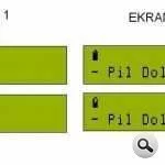
Program 0.5 volts the 10 steps as a battery character is reflected, level zero, no characters over in the sense flashing warning gives further charging pressing you to a different screen, state of charge batteries again to the character, as moving is reflected If you want different voltages can adapt to the ADC converter @ETE teacher’s notes that I used the program as a base, next to bless the program line are very descriptive definition, I extend my thanks to him. Author: Kerem Süzgün
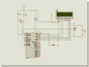
CHARGE STATUS, BATTERY CHARGING CIRCUIT SCHEMATIC
PIC16F877 Microcontroller Controlled LCD Screen Battery Charging Circuit PicBasic source code schematic files
FILE DOWNLOAD LINK LIST (in TXT format): LINKS-6833.zip
Source: MICROCONTROLLER CONTROLLED LCD SCREEN BATTERY CHARGING CIRCUIT PICBASIC PRO
- What microcontroller is used in the project?
The project uses the PIC16F877 microcontroller. - How is the charge status displayed?
Charge status is displayed on a 2 × 16 LCD screen. - Can the simulation be observed before building?
Yes, the circuit can be simulated and observed in ISIS (Proteus) simulation. - What programming language/tool was used for the firmware?
The firmware was prepared with PicBasic Pro. - What file types are provided as resources?
Provided resources include PbPr, ASM, and HEX files, and a LINKS-6833.zip download. - How does the project represent battery voltage steps?
The program reflects battery voltage in 0.5 volt steps across 10 steps. - Does the circuit provide warnings for low battery?
Yes, a flashing warning appears when the battery level is zero or below the defined threshold. - Can the ADC scaling be adapted to different voltages?
Yes, the ADC converter scaling can be adapted for different voltages as noted in the article. - Who is the author of the project?
The author is Kerem Süzgün.