Summary of MICROCHIP PIC16F877 TESTING, EXPERIMENT BOARD
This article details a PIC16F877 development board featuring a 7V–12V protected power supply, LED displays for PORTs A-E, eight logic inverters, and adjustable analog inputs via knobs. It includes serial communication capabilities using a MAX232 chip with specific pin modifications to avoid conflicts. The board supports in-circuit programming through a bootloader, utilizing push buttons for reset and program loading, and provides connectors for expansion.
Parts used in the PIC16F877 Experiment Board:
- PIC16F877 microcontroller
- MAX232 chip
- LED display (32 statements)
- Logic inverters (8 units)
- Potentiometers (knobs)
- HE10 connectors
- 4mm sockets
- Push button J7
- Resistors R3, R4, R5
- Jumpers J5 to J8
PIC16F877 Experiment board ACCEL P-CAD PCB PCB and schema files V14.00.3 asm code through the sample has been prepared by the addition You will find on this page all the elements to achieve a…Electronics Projects, Microchip PIC16F877 Testing, Experiment Board “pic development board, pic16f877 projects, “

PIC16F877 Experiment board ACCEL P-CAD PCB PCB and schema files V14.00.3 asm code through the sample has been prepared by the addition
You will find on this page all the elements to achieve a map of development for PIC16F877. s une application.it can be placed directly in an application. Reboul pour implanter le “bootloader” dans le PIC. We used the PIC sold 49.33 € 01 HT by institutions Reboul to implement the “bootloader” in the PIC. The program is most useful in the future, because the programming is done in situ using the serial port of a PC.
PIC16F877 DEVELOPMENT BOARD
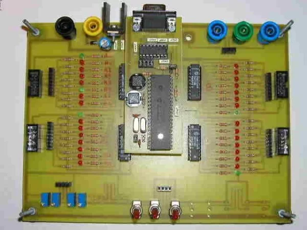
Card Features PIC_DEVEL: Power supply 7v to 12v protected against reverse polarity
LED display by 32 statements of PORTS A, B, C, D ETE
8 inverters to generate logic levels on inputs PIC
8 knobs to generate tension on adjustable analog inputs PIC
4 connectors to link HE10 entry / exit PIC to other cards
4 sockets to connect 4mm output of the ICP to a measuring device
The connections between potentiometers (or inverters or 4mm socket) and inputs / outputs of the PIC is with simple bare son inserted in a row connector contact.
MAX232 R4 and R5 are not on the pattern established: they were intercallées between MAX 232 (pin 9 et12) and PIC16f877 (RB2 and RB7). (He had cut the tracks that linked directly to the PIC Max) This allows for the pin RB2 and RC7 ICP output without creating conflict with the output of MAX232
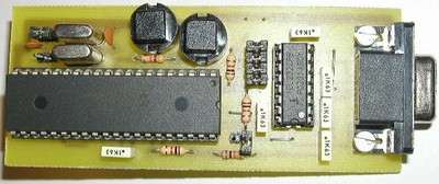
The jumpers J5 to J8 are unnecessary (to be replaced by son), Pins RB3, RC6, RB2 and RC7 CIP can easily be used as inputs or outputs in an application, the risk of conflict with the MAX are avoided thanks to R3 and R4.
The jumper J7 was replaced by a push button J7 not included in the scheme of establishment (see photo): J3 pressing Reset single product, while pressing J3 when J7 is already supported causes loading a program by the serial link. (this provided they use the bootloader “bootrt.asm” testing the RB1 Reset).
Source: stielec.free.fr/ Microchip PIC16F877 Testing, Experiment Board schematic pcb files alternative link: microchip-pic16f877-testing-experiment-board.rar alternative link2
- What is the power supply range for the board?
The board accepts a power supply from 7v to 12v which is protected against reverse polarity. - How many LEDs are available for PORT display?
The board features an LED display consisting of 32 statements covering PORTS A, B, C, D, and E. - Can the board be programmed in situ?
Yes, the program allows for programming in situ using the serial port of a PC after implementing the bootloader. - Why were jumpers J5 to J8 removed?
These jumpers are unnecessary and should be replaced by wire because the pins can easily function as inputs or outputs without conflict. - How do you load a program using the serial link?
You must press J3 while J7 is already supported to cause the loading of a program by the serial link. - What components generate tension on adjustable analog inputs?
Eight knobs are used to generate tension on the adjustable analog inputs for the PIC. - How are connections made between potentiometers and PIC inputs?
Connections are made using simple bare son inserted into a row connector contact. - What is the purpose of resistors R3 and R4?
R3 and R4 help avoid risks of conflict with the MAX232 when using pins RB3, RC6, RB2, and RC7.