


Summary of MCP4921 12 bit DAC interfacing with PIC16F877 microcontroller via SPI Connectivity
This tutorial explains interfacing an MCP4921 12-bit DAC with a PIC16F877 microcontroller via SPI to generate triangular waves. It details the 16-bit data transmission format, combining a 4-bit control word with 12-bit data to manage output gain and power states. The article calculates voltage resolution based on a 5V reference and provides specific hexadecimal examples for generating precise output voltages like 3V.Parts used in MCP4921 12 bit DAC Interfacing Project:
- MCP4921 12-bit DAC
- PIC16F877 Microcontroller
- SPI Connectivity Interface
- Analog Input Sensors (Contextual)
- Analog Output Devices (Contextual)
In any real time project, MCP4921 12 bit DAC interfacing with PIC16F877 microcontroller via SPI Connectivity is very essential. Because in real world most of the input sensors and output devices are analog. So if we want to work with those we need to know the basic interfacing of those sensors and output devices with microcontroller. Here I give you tutorial project on “MCP4921 12 bit DAC interfacing with PIC16F877 microcontroller via SPI Connectivity”.
Project description:
In this tutorial project we will see how we generate triangular Wave using MCP4921 12 bit DAC. As we know that MCP4921 is a 12 bit DAC. But the control word we have to send 16 bit including data. In below we see the bit structure for MCP4921.
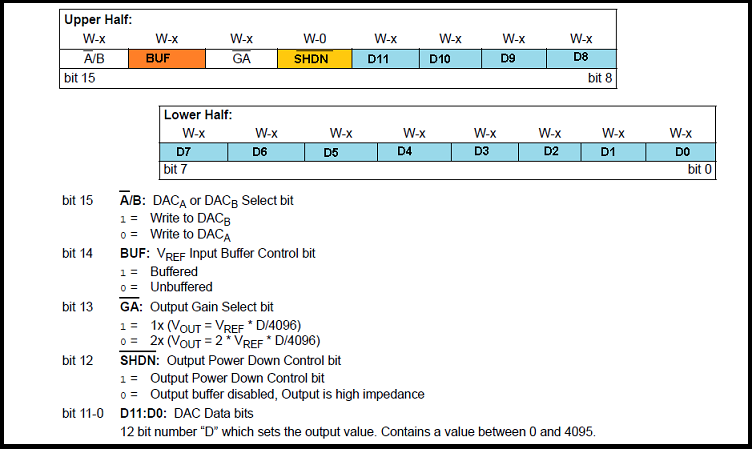
From above picture it is clear that bit 12-15 is used for control word and bit 0 to bit 11 are used for send 12 bit data.
Now question is how we maintain that format to send every 12 bit data along with 4 bit control word at MSB?
Let take an example if we want to write data via DCAA with output gain 1X and power down control bit.
So for that our control word will be
Bit 15 = 0 (write to DACA )
Bit 14 = 0 (Un buffered)
Bit 13 = 1(Output Gain)
Bit 12 = 1 (Output power down control)
So control bit will be 0011 = 3 .
So if you want to write 12 bit data like 001000100010. Then you have to send 16 bit data 0011001000100010 (0x32 and 0x22).
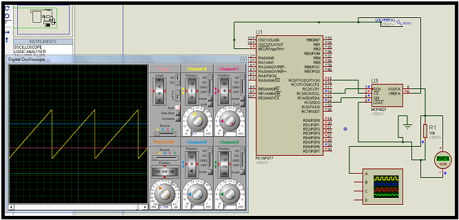
So we can get maximum 4096 different value by 12 bit data format. If we use 5V reference voltage then we will get ( 5000/4096) .001220703125 mile volt per step.
So for sending 3 volt at output we have to send 2.5/ .001220703125 = 2048 (010000000000) along with 3(0011) at MSB. So the final 16 bit data will be 0011010000000000 ( 0x34 and 0x00).
For more detail: MCP4921 12 bit DAC interfacing with PIC16F877 microcontroller via SPI Connectivity
-
Why is MCP4921 interfacing essential in real-time projects?
It is essential because most input sensors and output devices in the real world are analog. -
What waveform does this project generate using the MCP4921?
The project generates a triangular wave. -
How many bits are required to send data including the control word?
You must send 16 bits, which includes 4 bits for the control word and 12 bits for the data. -
Which bits are used for the control word versus the data?
Bits 12 through 15 are used for the control word, while bits 0 to 11 are used for sending 12-bit data. -
How do you set the output gain and power down control bits?
Bit 13 is set to 1 for Output Gain, and Bit 12 is set to 1 for Output power down control. -
How many different values can be obtained with the 12-bit data format?
You can get a maximum of 4096 different values. -
What is the voltage step size if using a 5V reference voltage?
The step size is approximately 0.001220703125 millivolts per step. -
How do you calculate the data value needed to output 3 volts?
You divide the desired voltage by the step size (2.5 divided by 0.001220703125) to get 2048.
Related projects
PIC16F877 Driving LCD in 4-Bit Mode using PIC16F877 with Proteus Simulation
Introduction This microcontroller project shows how a PIC16F877 can drive an LCD display using 4-bit mode inside a Proteus simulation.The project demonstrates...
Programmers & ICSP · PIC16F877AEPE PIC/LCD Demo using PIC16F877 with Proteus Simulation
IntroductionThe EPE PIC/LCD Demo is a classic microcontroller project that demonstrates how a PIC16F877 can fully control a PG12864F graphical LCD.Designed as...
Motors & Robotics · PIC16F877AEfficient Sun-Following Robot: A Solar Tracker with Microcontroller Control
Abstract The impending global challenge of dwindling non-renewable fuel resources underscores the urgency of transitioning towards renewable energy alternatives like solar power....
Communication & Interfacing · PIC18F4520CAN FD Node based on a PIC18 Microcontroller
The introduction sets the stage for an embedded systems project that involves developing a Embedded C CAN FD project using the MCP2517FD...
Communication & InterfacingLAN9662 Gigabit Switch: Optimized for Industrial Ethernet
Introduction It should come as little surprise therefore that one element of what is now more commonly referred to in some circles...
Communication & InterfacingPIC Microcontroller: Fundamentals & Applications for Students
Introduction Microcontrollers are the key components in the embedded systems market. A variety of embedded systems was formed and developed after the...

Ibrar Ayyub
I am an experienced technical writer holding a Master's degree in computer science from BZU Multan, Pakistan University. With a background spanning various industries, particularly in home automation and engineering, I have honed my skills in crafting clear and concise content. Proficient in leveraging infographics and diagrams, I strive to simplify complex concepts for readers. My strength lies in thorough...