MCP23X08 Evaluation Board using PIC10F202 with Proteus Simulation

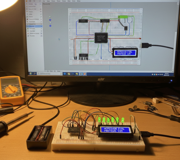
Summary of MCP23X08 Evaluation Board using PIC10F202 with Proteus Simulation


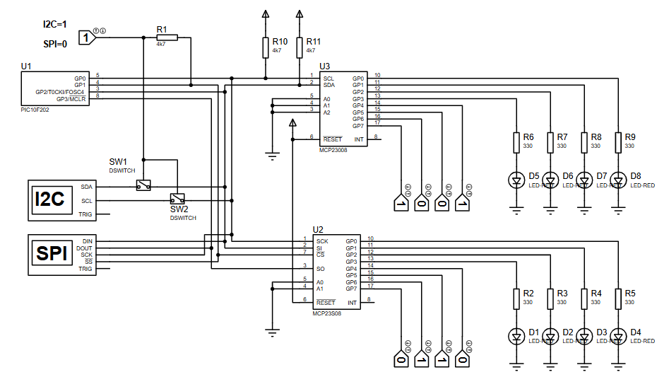
MCP23X08 evaluation board PIC10F202 demonstrates GPIO expansion using MCP23008 (I2C) and MCP23S08 (SPI) with bit-banged protocols on a PIC10F202. A toggle switch selects I2C or SPI; the PIC reads upper-nibble inputs from the expander, swaps bits as needed, and mirrors them to lower-nibble LEDs. Fully simulated in Proteus, the project is educational for protocol comparison, dynamic mode switching, and firmware-driven serial communication.

Parts used in the MCP23X08 evaluation board PIC10F202:

  • PIC10F202 microcontroller
  • MCP23008 I2C I/O expander
  • MCP23S08 SPI I/O expander
  • LEDs
  • Current-limiting resistors for LEDs
  • Toggle switch for protocol selection
  • Pull-up resistors for I2C lines
  • Proteus simulation software (for testing)

Introduction

MCP23X08 evaluation board PIC10F202 is a compact embedded systems project that demonstrates GPIO expansion using MCP23008 and MCP23S08 via I2C and SPI communication. This MCP23X08 evaluation board PIC10F202 uses bit-banged serial protocols on a PIC10F202 microcontroller and is fully simulated in Proteus for educational and protocol comparison purposes.

PIC MCP23X08 breadboard prototype demonstration

How the Project Works (Overview)

The PIC10F202 acts as the master controller and dynamically switches between I2C and SPI modes using a hardware toggle switch.
Depending on the selected mode, it communicates with either:

  • MCP23008 via I2C, or

  • MCP23S08 via SPI

The microcontroller reads input states from switches connected to the expander and mirrors those inputs onto LEDs. This bidirectional operation highlights real-world serial communication handling using firmware-driven (bit-banged) protocols.

Block Diagram / Workflow Explanation

  1. Mode Selection
    A toggle switch selects I2C or SPI communication.

  2. Initialization
    The PIC initializes GPIO direction registers on both expanders.

  3. Input Reading
    The upper nibble of the expander GPIO is read as digital inputs.

  4. Data Processing
    Input bits are swapped to align with LED outputs.

  5. Output Driving
    The lower nibble drives LEDs to reflect switch states.

  6. Continuous Monitoring
    The system loops, allowing live switching between I2C and SPI modes.

Key Features

  • Dual-protocol support (I2C and SPI) using a single microcontroller

  • Bit-banged serial communication without hardware peripherals

  • Dynamic mode switching during runtime

  • GPIO expansion using MCP23x08 devices

  • Real-time input-to-output mirroring

  • Fully simulated and testable in Proteus

Components Used

  • PIC10F202 microcontroller

  • MCP23008 (I2C I/O expander)

  • MCP23S08 (SPI I/O expander)

  • LEDs with current-limiting resistors

  • Toggle switch for protocol selection

  • Pull-up resistors for I2C lines

Applications

  • GPIO expansion in pin-limited microcontrollers

  • Learning I2C and SPI working principles

  • Embedded systems training and labs

  • Communication protocol comparison demos

  • DIY electronics projects requiring flexible interfaces

Explanation of Code (High-Level)

The firmware is written in MPASM assembly, optimized for the PIC10 architecture.
Key modules include:

  • I2C routines: Start, Stop, ACK/NACK, byte read/write

  • SPI routines: Mode 0 clocking, byte transfer, chip-select handling

  • Mode switching logic: Detects toggle switch state and reconfigures peripherals

  • GPIO handling: Reads inputs and updates outputs through expander registers

The code carefully manages TRIS behavior since the PIC10F202 lacks a dedicated TRIS register, making this project especially educational.

Source Code

Download
	#include         ; processor specific variable definitions
;	#include         ; processor specific variable definitions

	__CONFIG   _MCLRE_OFF & _WDT_ON & _IntRC_OSC 

; '__CONFIG' directive is used to embed configuration word within .asm file.
; The lables following the directive are located in the respective .inc file.
; See data sheet for additional information on configuration word sett

Proteus Simulation

In Proteus, the simulation allows you to:

  • Toggle between I2C and SPI modes live

  • Observe GPIO changes on LEDs instantly

  • Verify correct ACK/NACK handling

  • Debug serial timing visually

The simulation behaves exactly like real hardware, making it ideal for learning and troubleshooting without physical components.

(FAQs)

1: Why is bit-banging used instead of hardware I2C/SPI?

Because the PIC10F202 does not include built-in serial peripherals.

2: Can this project run on real hardware?

Yes, the code is hardware-ready and based on Microchip’s official application note.

3: Why is RAMTRIS used instead of TRIS?

PIC10 baseline devices require manual tracking of pin direction.

4: Can I replace MCP23x08 with other expanders?

Only compatible devices with similar register maps will work without code changes.

5: What clock speed is used?

The internal RC oscillator with factory calibration.

6: Can this be expanded to more I/O lines?

Yes, multiple expanders can be chained using address pins.

7: Is this suitable for beginners?

Yes, but basic understanding of embedded systems and serial communication helps.

Conclusion

This project is an excellent demonstration of efficient embedded systems design using minimal hardware resources. It shows how a tiny PIC microcontroller can handle complex serial communication, expand GPIO capability, and dynamically manage protocols.
Whether you’re learning Proteus simulation, firmware development, or communication fundamentals, this project delivers strong practical value and real-world relevance.

Quick Solutions to Questions related to MCP23X08 evaluation board PIC10F202:

  • How does the project switch between I2C and SPI?
    A hardware toggle switch selects I2C or SPI and the PIC10F202 dynamically switches modes in firmware.
  • Can this project run on real hardware?
    Yes, the article states the code is hardware-ready and based on Microchip’s application note.
  • Why is bit-banging used instead of hardware I2C or SPI?
    Because the PIC10F202 does not include built-in serial peripherals.
  • What expanders are used for I2C and SPI?
    MCP23008 is used for I2C and MCP23S08 is used for SPI.
  • How are inputs and outputs mapped on the expander?
    The upper nibble of the expander GPIO is read as inputs and the lower nibble drives LEDs after bit swapping.
  • What oscillator clock is used for the PIC10F202?
    The internal RC oscillator with factory calibration is used.
  • Why is RAMTRIS used instead of TRIS?
    PIC10 baseline devices require manual tracking of pin direction, so RAMTRIS is used.
  • Can more I/O be added to this design?
    Yes; multiple expanders can be chained using address pins according to the article.
  • Is Proteus used in this project?
    Yes, the project is fully simulated and testable in Proteus for live mode switching and debugging.
  • Is this project suitable for beginners?
    The article says yes, but a basic understanding of embedded systems and serial communication helps.

About The Author

Ibrar Ayyub

I am an experienced technical writer holding a Master's degree in computer science from BZU Multan, Pakistan University. With a background spanning various industries, particularly in home automation and engineering, I have honed my skills in crafting clear and concise content. Proficient in leveraging infographics and diagrams, I strive to simplify complex concepts for readers. My strength lies in thorough research and presenting information in a structured and logical format.

Follow Us:
LinkedinTwitter