Sensored BLDC Motor Control using dsPIC33FJ12MC202 with Proteus Simulation

Summary of Sensored BLDC Motor Control using dsPIC33FJ12MC202 with Proteus Simulation


This project demonstrates sensored BLDC motor control using a dsPIC33FJ12MC202 in a Proteus simulation, combining Hall sensors, MCPWM, ADC-triggered sampling, and timers for commutation and speed control. A potentiometer provides duty-cycle speed input; Input Capture and Timer 3 measure rotor speed. The firmware follows Microchip AN957 and initializes ADC, MCPWM, Input Capture, and timers for synchronized, deterministic motor control and is suitable for learning and firmware validation before hardware tests.

Parts used in the Sensored BLDC Motor Control using dsPIC33FJ12MC202 with Proteus Simulation:

  • dsPIC33FJ12MC202 microcontroller
  • BLDC motor (star connected)
  • Hall effect sensors (A, B, C)
  • Potentiometer (speed input)
  • Resistors (pull-ups, current limiting)
  • LEDs (status indication)
  • MCPWM hardware module (on dsPIC)
  • Timers (TMR1, TMR3)
  • Proteus VSM simulation environment

Introduction

This microcontroller project demonstrates sensored BLDC motor control using a dsPIC33FJ12MC202 and a complete Proteus simulation environment.
Based on Microchip Application Note AN957, the project shows how Hall sensors, PWM generation, ADC input, and timers work together for reliable motor commutation and speed control.
It is a practical embedded systems example for anyone learning motor control, dsPIC PWM modules, and real-time firmware design.
The project is ideal for students and engineers exploring DIY electronics, BLDC fundamentals, and motor control firmware in simulation before hardware testing.

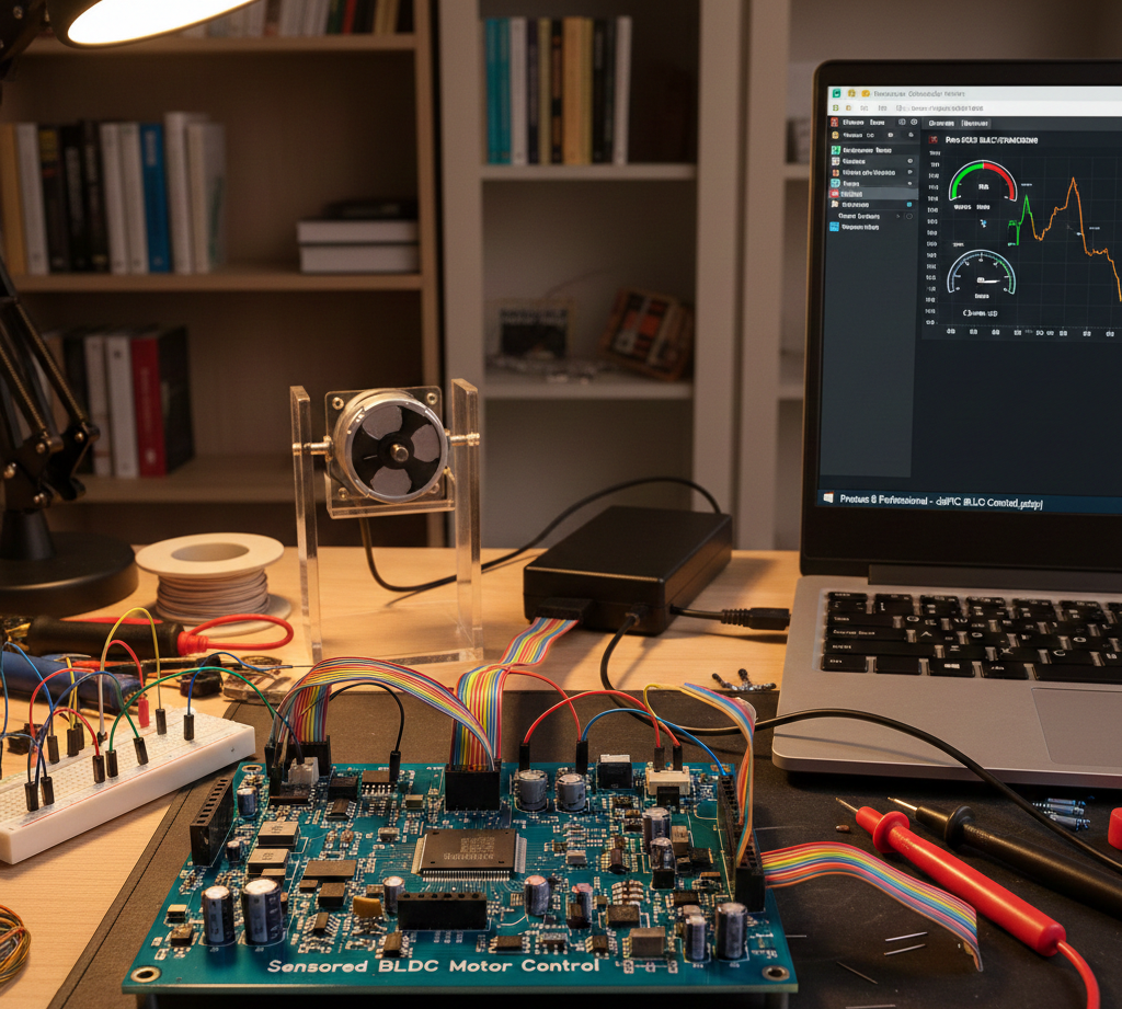
BLDC motor control setup
Illustrative View of the Concept.

How the Project Works (Overview)

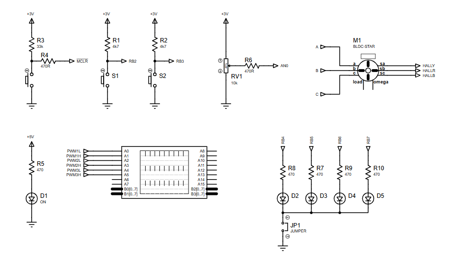
The system controls a sensored BLDC motor using three Hall-effect signals to determine rotor position.
The dsPIC33 reads Hall transitions through Input Capture modules, calculates timing using Timer 3, and updates commutation through the Motor Control PWM (MCPWM) module.
A potentiometer connected to the ADC provides duty-cycle control, allowing real-time speed variation.
PWM triggers ADC sampling, ensuring synchronized control between motor drive and feedback.

Block Diagram / Workflow Explanation

  1. Potentiometer (AN0) provides speed reference

  2. ADC module samples speed command

  3. MCPWM module generates three independent PWM signals

  4. Hall sensors (A, B, C) feed rotor position into Input Capture modules

  5. Timer 3 measures rotor speed using Hall transitions

  6. OVDCON logic updates PWM outputs for proper commutation

  7. BLDC motor responds with controlled speed and direction

Key Features (Auto-Generated)

  • Sensored BLDC motor commutation using Hall feedback

  • Independent PWM generation via dsPIC MCPWM module

  • ADC-based speed control using a potentiometer

  • PWM-triggered ADC sampling for synchronized control

  • Rotor speed measurement using Input Capture + Timer 3

  • Designed for Proteus simulation and firmware testing

  • Based on Microchip Application Note AN957

Components Used

  • dsPIC33FJ12MC202 microcontroller

  • BLDC motor (star connected)

  • Hall effect sensors (A, B, C)

  • Potentiometer (speed input)

  • Resistors (pull-ups, current limiting)

  • LEDs (status indication)

  • MCPWM hardware module

  • Timers (TMR1, TMR3)

Applications

  • BLDC motor speed control systems

  • Robotics and motion control platforms

  • Educational motor control labs

  • Industrial motor drive prototypes

  • Embedded systems learning projects

  • Simulation-based firmware validation

Explanation of the Code (High-Level)

The firmware initializes and coordinates multiple dsPIC peripherals:

  • ADC Initialization (InitADC10)
    Configures single-channel ADC input for the potentiometer. ADC conversion is triggered by PWM for synchronized sampling.

  • PWM Initialization (InitMCPWM)
    Sets PWM frequency (~39 kHz), enables independent PWM outputs, and prepares duty-cycle registers for real-time updates.

  • Hall Sensor Input Capture (InitIC)
    Configures Input Capture modules to detect Hall sensor transitions. One channel is used for speed calculation, others for commutation.

  • Timer 3 (InitTMR3)
    Measures rotor speed by timing Hall transitions using a prescaled system clock.

  • Timer 1 (InitTMR1)
    Provides a fixed periodic interrupt (1 kHz) for background control tasks.

This modular structure keeps motor control logic deterministic and efficient.

Source Code

Download
	File:		Init.c
//
//	Written By:		Bill Anderson, Microchip Technology
//						
// 
// The following files should be included in the MPLAB project:
//
//		SensoredBLDC.c		-- Main source code file
//		Interrupts.c
//		Init.c
//		SensoredBLDC.h		-- Header file
//		p33FJ256MC710.gld	-- Linker script file
//				

Proteus Simulation

In Proteus VSM, the dsPIC33 drives a simulated BLDC motor using Hall feedback.
Changing the potentiometer value alters ADC readings, which directly adjust PWM duty cycle.
Hall sensor transitions are visible through Input Capture events, confirming correct commutation timing and speed response.

(FAQs)

1. Why use Hall sensors in BLDC control?

They provide accurate rotor position for reliable commutation.

2. Can this project run without hardware?

Yes, it is fully designed for Proteus simulation.

3. Which PWM mode is used?

Independent PWM mode with output override control.

4. How is motor speed measured?

Using Hall sensor transitions timed by Timer 3.

5. Can the PWM frequency be changed?

Yes, by modifying FPWM and PTPER.

6. Is this compatible with other dsPIC33 devices?

Conceptually yes, but register mapping may differ.

7. Why trigger ADC from PWM?

It ensures synchronized sampling with motor switching.

8. Can this be extended to closed-loop speed control?

Yes, by adding a PID controller in firmware.

Conclusion

This project is an excellent embedded systems learning example for sensored BLDC motor control using a dsPIC33 microcontroller.
With structured firmware, real-time peripherals, and Proteus simulation, it provides strong practical insight into motor control firmware design.
Ideal for students, hobbyists, and engineers building confidence in microcontroller projects and motor control systems.

Quick Solutions to Questions related to Sensored BLDC Motor Control using dsPIC33FJ12MC202 with Proteus Simulation:

  • Why use Hall sensors in BLDC control?
    They provide accurate rotor position for reliable commutation.
  • Can this project run without hardware?
    Yes, it is fully designed for Proteus simulation.
  • Which PWM mode is used?
    Independent PWM mode with output override control.
  • How is motor speed measured?
    Using Hall sensor transitions timed by Timer 3.
  • Can the PWM frequency be changed?
    Yes, by modifying FPWM and PTPER.
  • Is this compatible with other dsPIC33 devices?
    Conceptually yes, but register mapping may differ.
  • Why trigger ADC from PWM?
    It ensures synchronized sampling with motor switching.
  • Can this be extended to closed-loop speed control?
    Yes, by adding a PID controller in firmware.

About The Author

Ibrar Ayyub

I am an experienced technical writer holding a Master's degree in computer science from BZU Multan, Pakistan University. With a background spanning various industries, particularly in home automation and engineering, I have honed my skills in crafting clear and concise content. Proficient in leveraging infographics and diagrams, I strive to simplify complex concepts for readers. My strength lies in thorough research and presenting information in a structured and logical format.

Follow Us:
LinkedinTwitter