
Summary of Low Resource Microcontroller – 3 Phase BLDC Motor Speed Controller
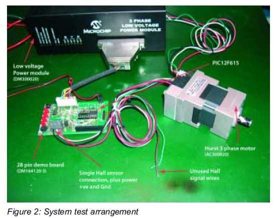
This article describes a minimal-resource design for closed-loop 3-phase BLDC motor speed control using a Microchip PIC12 microcontroller, reducing I/O to six by using one Hall sensor, multifunction pins, PWM steering, reconstructed high-side drive, and creative use of the microcontroller power/reset for over-current protection. It targets low-cost fan and pump applications and details practical pin-sharing, analog/read-before-run, stop detection, and use of PIC12F615/PIC12HV615 peripherals to implement six-step commutation with only required PWM on one low-side at a time.
Parts used in the Low Resource Microcontroller - 3 Phase BLDC Motor Speed Controller:
- Microchip PIC12F615 or PIC12HV615 microcontroller
- 3-phase BLDC motor with single Hall sensor
- 3-phase power bridge (high side and low side transistors)
- Resistors for reconstructing third high-side drive
- Transistor inverter for reconstructed high-side drive
- Potentiometer for speed setting
- Resistive divider chain for analog input/speed setting
- Start and stop switches
- Motor over-current trip circuit (external, interrupts PIC supply via resistor to internal shunt regulator)
- Pull-up resistor for Hall sensor open-collector output
This could form the basis where high performance is not required
This article focuses on a minimal resource microcontroller implementation for a 3 phase BLDC motor, closed loop speed motor controller application based on a Microchip PIC12 device. It shows how minimisation techniques can reduce the number of I/O pins to just 6 for this type of application. It assumes the reader understands the commutation sequence for the aforementioned type of motor.
Just how small a microcontroller can control a 3 phase BLDC motor? Well to answer that question requires the chip resources to be identified which align with the external BLDC motor control topology and functionality for the intended application. If at the outset we address the low cost volume market for speed control applications used in fans and pumps the problem narrows down. In relation to this type of system there are those with sensor and sensor-less configurations (for determining rotor position) which both offer pros and cons but in terms of I/O count if the rotor position sensing can be done on one pin we are off to a good start. Also if multi function pins can be deployed for a simple user interface and logic minimization techniques can reduce the pin count further then the minimal resource map for a suitable device can be approached.
 BLDC Motor Control System
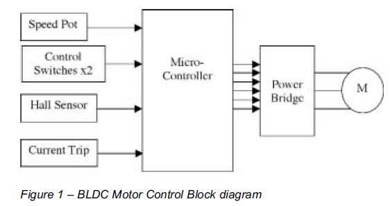
In Figure 1, the block diagram illustrates a system using a single Hall sensor for rotor position feedback (many systems use 3 for this purpose), a potentiometer for speed setting, a start and stop switch, a motor over current trip and a 3 phase power bridge to drive the motor. The resulting amount of independent connections to the microcontroller shown between the system sub components is 11 (5 inputs and 6 outputs). However, minimisation can be accomplished if the microcontroller supports multi function pins and ubiquitous peripherals.
Resource minimization techniques
Considering the microcontroller output signals to the 3 phase power bridge, if the BLDC six step control algorithm is deployed then only two transistors are ON at any time during normal running i.e. one high side and one low side transistor and these are driven in non complementary fashion. So the high and low side transistors are from different half bridge configurations and are driven in the so called diagonal mode. This is advantageous from a logic minimisation perspective because when two of the three high side devices are OFF in run mode, the third should be ON. Hence the third high side output signal can be reconstructed from the other two via a few resistors and transistor inverter which connects to the third High side power bridge input (ref Figure 4 – Circuit diagram). This leads to a reduction of microcontroller pins. So we have gone from a system requiring 6 outputs to one requiring 5.
With respect to the five system inputs for a Hall sensor, potentiometer, motor current trip and start/stop switches there are various possibilities. Firstly the Hall sensor(s) are commonly built into the BLDC motor assembly and these tend to have also integrated circuitry for a digital interface to the microcontroller. This can take the form of open collector style transistor outputs and a pull up resistor is provided at the external motor controller end for signal detection. In this application one Hall sensor is required and the PIC12F device family feature one digital input only pin that can be used for this purpose.
For the motor start and speed setting function, at power up one of the 3 phase power bridge high side drive pins can be configured as an analogue input. This pin is connected to a resistive divider and potentiometer. Hence before the motor is run the speed can be set and read. In addition the addition of a start switch which can reduce the speed setting below a minimum can also enable motor starting. In this analogue input mode, although the connected high side drive transistor is turned on this does not result in motor energization as all the low side drive transistors are off at this time. Subsequently, in run mode the pin is configured as an output for motor high side transistor driving and then the resistive divide chain effectively becomes a pin pull up/down function.
The stop function is best implemented separately when the motor has started and not by using the start switch as a combined start/stop function during the commutation sequence. Hence the stop function is implemented in firmware via a rotation timeout i.e. when the stop switch is pressed in run mode the high side drive signals are all disabled and the firmware can detect the subsequent motor stall condition and place the application into stop mode. An even more elementary motor stop function could be implemented by using a normally open switch in parallel with the over current trip circuit described below.
The over current trip does not use any of the microcontroller I/O pins; instead it makes use of the high voltage PIC12 family variant’s power supply connection in order to reset the device due to motor over current. This type of PIC deploys an internal shunt regulator which is connected to the application power supply via a resistor. The resistor is sized according to the application requirements. Hence the supply can be interrupted to the PIC via the over current trip circuit which is effectively connected in parallel with the internal supply regulator.
 So we now have a system that requires microcontroller I/O pins with 1 dedicated digital input, 1 digital/analogue and 4 digital output functions. However, we have ignored the fact that for speed control we will need to modulate the applied voltage to the BLDC motor and for this we require some PWM signals to be applied to, in this case, the low side drive transistors. In fact, because six step control is implemented, the requirement is to have any one of the three low side drivers supplied with a PWM signal at any instant in time during the motor commutation sequence. Some PIC devices feature a specific Motor Control PWM peripheral for this purpose whereas others have PWM signal steering capability to 1 of n outputs to basically achieve the same via for example an ECCP (Enhanced Capture/Compare Peripheral). On a PIC12F we have a combination of PWM signal steering in the ECCP and alternative pin configuration modes available (APCFG). This is extremely convenient because the PWM steering can only be done on two pins via the ECCP and the application requires three (via the APCFG mode). Only the PIC12F615 and PIC12HV615, currently, have this capability.
For more detail: Low Resource Microcontroller – 3 Phase BLDC Motor Speed Controller
- How small a microcontroller can control a 3 phase BLDC motor?
The article demonstrates control using a PIC12 family device, reducing required I/O to six for this application. - Can a single Hall sensor be used for rotor position feedback?
Yes, the design uses a single Hall sensor for rotor position feedback. - How is the number of microcontroller outputs reduced for the high side drives?
The third high-side output is reconstructed from the other two using resistors and a transistor inverter, reducing outputs from six to five. - Can a high side drive pin be used as an analog input for speed setting?
Yes, at power up a high side drive pin is configured as an analog input connected to a resistive divider and potentiometer to read speed before running. - How is motor stopping implemented?
Stop is implemented in firmware via a rotation timeout when the stop switch is pressed in run mode; an elementary alternative uses a normally open switch in parallel with the over-current trip. - Does the over current trip use a microcontroller I/O pin?
No, it uses the PIC12 high-voltage variant power supply and internal shunt regulator via an external resistor to reset the device on over current. - How is PWM applied for speed control in six-step commutation?
Only one of the three low-side drivers needs a PWM signal at any instant; PWM steering in ECCP plus APCFG modes on PIC12F allows routing PWM to required pins. - Which PIC12 devices support the required PWM steering and alternative pin configuration?
Only the PIC12F615 and PIC12HV615 currently have the required PWM steering and APCFG capability.
