
Summary of Long Period Astable Timer using PIC12F629
This project implements a long-period astable multivibrator on a PIC12F629/12F675, producing mark/space intervals from 1 to 65,535 seconds, with up to 450 sequential time pairs, edge-triggered reset (configurable rising/falling), and an active-low hold that stretches the current period. Timings use the internal 4 MHz RC oscillator (≈99% accuracy after calibration); recommended to calibrate at the intended supply voltage and test accuracy before deployment.
Parts used in the Long Period Astable Timer:
- PIC12F629 microcontroller (or PIC12F675)
- Power supply (suitable for PIC operating voltage, e.g., 5V)
- Connections for Reset input (configurable edge)
- Connections for Hold input (active low)
- Output connections for Q and notQ
- LongDelayTimes.inc timing data file (software component)
- Optional programmer for PIC calibration and programming
Description
This software functions as a long period astable mutivibrator. The mark and space period can be set from 1 second up to a maximum 65535 seconds (18h12m15s). Using the internal 4Mhz RC oscillator delays with an accuracy of 99% or better can be achieved
The code also implements an edge triggered reset and an active low hold function. The reset edge can be configured for rising or falling edge. The hold function is active low and stretches the timed period for as long as the hold input is held low.
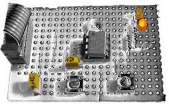
In addition to this up to 450 mark/space time pairs can be used which are executed sequentially allowing complex pulse trains to be generated.
By connecting the hold input to the Q output, the code can also be made to function as an edge-triggered monostable timer, using the reset input as the trigger.
The code will run on a PIC 12F629 or 12F675.
At power on and after an edge triggered reset the outputs enter a mark state with the Q output going high and the notQ output going low. The first time entry is then read and the code waits for the number of seconds specified. When this period has elapsed a Space state is entered with the Q output going low, notQ output high and the next time entry is read.
When the Hold input is taken low the output remains unchanged and the timer is stopped, effectively stretching the current time period. When the Hold input returns high, the timer continues.
If the Reset input is triggered while Hold is low, the outputs are reset to Q == high, notQ == low and the timer is loaded with the first entry from the LongDelayTimes.inc file. It them remains in the Hold state until the Hold input returns high.
Accuracy of timings
Since the timings are generated from the PICs internal 4Mhz RC oscillator the accuracy is subject to the tolerances specified in the Datasheet with respect to operating voltage and temperature. The software itself will generate an accurate timing but any deviation in the RC oscillator from 4Mhz will result in the time period deviating. You should therefore test the accuracy before committing it to an application.
Since the PIC calibration word can only be correct at a specific supply voltage and temperature it is advisable to calibrate it at the supply voltage it will operate at in the final application. This will help considerably in obtaining accurate timings.
My investigations with a number of PICs from different batches suggest that Microchip calibrate the PIC at a supply voltage of 3.5 volts. Therefore if you’re operating it from a 5 volt supply it will be running slightly too fast.
In the trace below the factory calibration value was 0x2C, the value when recalibrated with a 5 volt supply was 0x34. For a programmed delay of 60 / 300 seconds it is showing 59.85/ 299.3 seconds which is 99.7% accurate. This would result in an error of 3m16s over 18h12m.
For more detail: Long Period Astable Timer using PIC12F629
- What PICs will this code run on?
The code will run on a PIC12F629 or PIC12F675. - What range of mark and space periods can be set?
Mark and space periods can be set from 1 second up to 65535 seconds (18h12m15s). - How many sequential time pairs can be used?
Up to 450 mark/space time pairs can be used and executed sequentially. - How does the hold function behave?
The hold input is active low; when held low the output remains unchanged and the timer is stopped, stretching the current period until hold returns high. - How does reset behave when hold is low?
If Reset is triggered while Hold is low, outputs reset to Q high and notQ low, timer loads the first entry from LongDelayTimes.inc, and remains in Hold until Hold returns high. - What accuracy can be expected from the timings?
Using the internal 4 MHz RC oscillator, delays with an accuracy of 99% or better can be achieved after calibration; actual accuracy depends on oscillator tolerance with supply voltage and temperature. - Should I calibrate the PIC and at what voltage?
Yes; calibrate the PIC at the supply voltage it will operate at in the final application to improve timing accuracy. - Can this be used as an edge-triggered monostable?
Yes; by connecting the hold input to Q, the code functions as an edge-triggered monostable using Reset as the trigger.
