Summary of LCD DISPLAY FAN CONTROL CIRCUIT PIC16F84A PICBASIC PRO
This project uses a PIC16F84A microcontroller and DS18B20 temperature sensor to display ambient temperature on a 16x2 LCD, sound an alarm when a user-set temperature is exceeded, and control a fan to maintain the desired temperature. User setpoints are saved to EEPROM to survive power loss, and plus/minus buttons adjust the target temperature. Files include schematic, PCB layouts, Proteus simulation, and PicBasic Pro source code.
Parts used in the LCD DISPLAY FAN CONTROL CIRCUIT PIC16F84A PICBASIC PRO:
- PIC16F84A microcontroller
- DS18B20 temperature sensor
- 16x2 LCD display
- Buzzer or audible alarm
- Fan (DC)
- Plus (+) button
- Minus (-) button
- EEPROM (internal to PIC16F84A or external if used)
- Power supply components (regulator, capacitors)
- Transistor or driver for fan
- Resistors and pull-up for DS18B20
- PCB and connectors
This circuit and the microcontroller PIC16F84A DS18B20 temperature information is obtained using the temperature sensor. 16X2 LCD screen showing temperature information obtained from user-specified temperature is exceeded audible warning. The ambient temperature value drops to the desired level of… Electronics Projects, LCD Display Fan Control Circuit PIC16F84A Picbasic Pro “microchip projects, microcontroller projects, pic16f84 projects, picbasic pro examples,
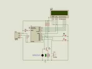
This circuit and the microcontroller PIC16F84A DS18B20 temperature information is obtained using the temperature sensor. 16X2 LCD screen showing temperature information obtained from user-specified temperature is exceeded audible warning. The ambient temperature value drops to the desired level of the fan keeps up. In addition to user-specified EEPROM heat value recorded in any power outages, loss of information is prohibited. Plus (+) and minus (-) buttons required for the operation of the fan allows you to set the temperature level.
PIC16F84A FAN CONTROL SCHEMATIC
PIC16F84A FAN CONTROL PCB TOP
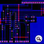
PIC16F84A LCD Display Fan Control Circuit proteus isis simulaiton schematic proteus ares PCB and pic16f84 picbasic pro source code files
FILE DOWNLOAD LINK LIST (in TXT format): LINKS-3385.zip
Source: LCD DISPLAY FAN CONTROL CIRCUIT PIC16F84A PICBASIC PRO
- How is temperature measured in this project?
Temperature is measured using a DS18B20 temperature sensor connected to the PIC16F84A. - How is temperature displayed to the user?
The measured temperature is shown on a 16x2 LCD display. - Can the user set a target temperature?
Yes, the user can set the target temperature using plus and minus buttons. - Does the system provide an audible warning?
Yes, an audible alarm sounds when the measured temperature exceeds the user-specified value. - How does the fan respond to temperature changes?
The fan runs to lower ambient temperature when the temperature exceeds the desired setpoint. - Are user settings preserved during power loss?
Yes, the user-specified temperature is stored in EEPROM to prevent loss during power outages. - What software and files are provided with the project?
Provided files include schematic, PCB layouts, Proteus simulation, and PicBasic Pro source code, available in a ZIP download. - Is there a simulation available for this circuit?
Yes, a Proteus ISIS simulation schematic is included with the project files.