Summary of LC meter using PIC16F628A Microcontroller
Summary: I built Phil Rice's LC meter, adding a compact battery-powered supply, USB charging, and minor firmware tweaks for improved display and auto-recalibration. The original measurement algorithm was kept intact while the device was made smaller and portable.
Parts used in the LC meter project:
- PIC16F628A microcontroller
- 16x2 LCD display (compatible with 5V)
- TPS61222 5V boost converter (Texas Instruments)
- Inductor/coil for TPS61222
- Decoupling and output capacitors for TPS61222
- MAX1811 Li-Ion charger IC (Maxim)
- 3.6V Li-Ion battery (135 mAh, from Bluetooth headset)
- USB connector for charging
- Project enclosure/box
- Miscellaneous passive components and PCB wiring
I needed a good LC meter for my one of my next projects so I went and built the famous LC meter by Phil Rice. This LC meter design is pretty old but since it is a perfectly good device there was no need to design/build/debug one of my own. So, I just changed the original firmware a bit and added few electronic goodies to it to make it more compact.
UPDATE: Project is on HackedGadgets, …and now also on Hack-a-Day!
Power Supply
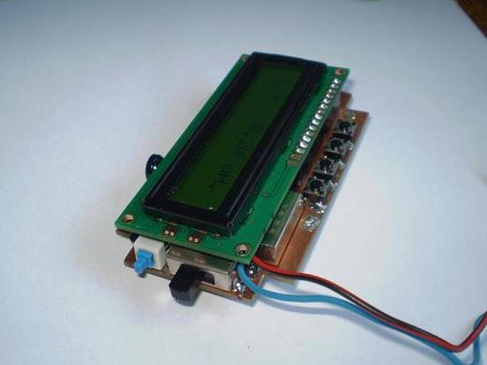
I wanted to fit it in this project box that I had laying around for some time and I also wanted it to be battery powered. There was no way that I could fit 9V battery in this project box along side with all the electronics, so I figured I could add a tiny 3.6V Li-Ion battery that I also had… laying around.
It is a 135mAh one from a broken Bluetooth headset. After having no luck in finding the appropriate 2×16 or 1×16 LCD that works at 3.6V I decided to incorporate a 5V voltage booster that will do the trick. For this purpose I selected TPS61222 power booster from Texas Instruments. This little (extremely little) device is very good and it requires just a coil and two capacitors to operate.
Now, because there is a Li-Ion battery in the device I needed a way to charge it properly. This is done by MAX1811 Li-Ion charger IC from Maxim. Later on, by placing a small USB connector on board, all power supply & charging problems were solved.
Firmware modifications
No critical firmware modifications were made. All calculations are performed as they were in the original firmware. Only a few small changes were made such as: PORTB pinout re-arranged for LCD display, second line of display constantly shows oscillator frequency, LC meter is automatically re-calibrated (“zeroed”) when switching from L to C and the other way around.
For more detail: LC meter using PIC16F628A Microcontroller
- What microcontroller is used in this LC meter?
The PIC16F628A microcontroller is used. - Can the device be battery powered?
Yes, it was made battery powered using a 3.6V Li-Ion 135 mAh battery. - How is 5V supplied for the LCD when using a 3.6V battery?
A TPS61222 boost converter is used to generate 5V from the 3.6V Li-Ion battery. - How is the Li-Ion battery charged?
Battery charging is handled by a MAX1811 Li-Ion charger IC and a USB connector was added for charging. - Were there major firmware changes to the original design?
No, only minor firmware changes were made; calculations remain as in the original firmware. - What firmware features were added or changed?
Changes include rearranged PORTB pinout for the LCD, the second LCD line showing oscillator frequency continuously, and automatic recalibration when switching between L and C modes. - Is the original LC measurement algorithm preserved?
Yes, all calculations are performed as they were in the original firmware. - Why was a small Li-Ion battery chosen instead of a 9V battery?
A 9V battery would not fit in the chosen project box, so a small 3.6V Li-Ion battery was used to make the device compact.