Summary of Lazer Duel
Summary: We built a two-player Lazer Duel laser-tag system with IR-based shooting/detection and a PIC32-controlled base station coordinating play via Nordic nRF24L01+ ultra low power RF transceivers. Each gun emits 38 kHz IR when fired, detects hits, updates health (8 lives start), plays sounds, and reports status to a TFT-equipped base station that shows lives, accepts joins, and ends the game when a player hits zero lives.
Parts used in the Lazer Duel:
- PIC32 microcontroller
- Nordic nRF24L01+ RF transceiver modules
- Infrared emitters (IR LEDs)
- Infrared detectors/receivers
- TFT display for base station
- 74HC595 8-bit shift register
- LM386 audio amplifier
- Speaker
- 4-bit DAC via CVREF (PIC32 CVREF output)
- 6V battery pack (power for LM386 and system)
- Push buttons (base station and gun controls/trigger)
- LEDs (red shoot LED, green life LED, and 8 life LEDs)
- Resistors and capacitors for amplifier and general circuitry (including 10K trimpot, 10 ohm resistor)
- SPI interface wiring (for radio and shift register)
- Prototyping/solder board and wiring
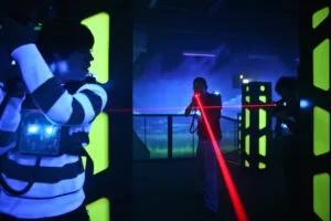
For our ECE 4760 final project, we designed and built a Lazer Duel game system involving two guns and a base station commucating over ultra low power RF tranceivers. We can shoot and detect shooting useing an IR emitter/receiver on the guns. The base station will coordinate the game by allowing two players to join and will end the game once a player loses all lives. All communication between the guns and the base station will be done wirelessly using the RF transeiver.
Our design achieves full functionality by allowing two players, each wielding a “lazer” gun to run around and shoot each other within a range of 20 meters. We also implemented sound effects such as the futuristic gun sounds to further enhance player experience. The base stations uses a TFT display to keep track of player lives and will signal both guns via radio to end the game once a player loses all lives.
Introduction
For our project we created a simple laser tag game where two players attempt to shoot each other with infrared “guns” and the last person standing is the winner. We also constructed a base station that keeps track of score by communicating with the two guns over radio. Each gun has an infrared emitter for shooting and an infrared detector that detects if the player using the gun was shot. We designed the shooting mechanism such that when the player presses a trigger on the gun a 38 kHz infrared wave will be emitted. If such IR radiation is detected by another gun, then the shot registers as a hit and the player being hit will lose one point of health. Each player starts off with 8 health and the game will end once a player reaches 0 lives, or if someone operating the basestation signals to end the game early. We equipped the guns with a ultra low power radio that sends vital statistics about the player such as player health and player identification to the base station.
The base station organizes the game for all the players that have joined. We have constructed two guns meaning only two players will be able to play per game. However, our code can be expanded to include even more players provided we build a few more guns. The base stations starts by actively listening for guns that want to join the game. Meanwhile, the players with the guns will press their trigger to send a request to join, which the base station will accept. Once all the players have joined, the base station will transition to the play game state and send out a signal to all the players to begin playing. During this state, the base station will recieve information about each player’s health level over the radio and display it on a TFT screen. Once a player loses all health or another button is pressed on the base station to end the game early, the base station will terminate the game and signal to the players that the game is over. The winner will be determined by which player has the most health at the end of the game, and that winner will be displayed onto the TFT.
Our project primarily show cases the functionality of the Nordic nRF24L01 radio tranceiver which is currently one of the most popular, low cost, ultra low power radio modules on the market. Since no functional radio library for the nRF24L01 currently exists for the PIC32 Microcontroller, we decided to start from scratch and implement our own library. We managed to implement a minimal radio library capable of sending and receving our own project specific message payloads. However, our eventual goal was to implement a fully functional radio library for future ECE4760 classes capable of being adopted by any PIC32 projects requiring a radio. Since we had limited time to implement on this final project, we plan on further completing the nRF24L01 library for the PIC32 in an Independent Study in the coming semester.
High Level Design
Project Rationale
The idea for our project evolved over time from a fireman survival kit, to an IR keyboard-less piano, but eventually we decided on a laser tag game. We originally wanted to create some kind of gas and fire detector that could detect dangers present in a hazardous environment and radio to base stations on the firetruck any present danger for the firemen. We were inspired to use radio over other wireless communication devices such as NFC or Bluetooth due to its longer range and because we had experience from an earlier class where we used a radio to send data from a maze mapping robot to a base station (ECE 3400). Unfortunately, there was no viable or safe way to unleash toxic gases or set a room on fire for our eventual project demonstration, so we decided to change our project. We came up with another idea where we wanted to implement a keyboardless piano that would use infrared emitter detector pairs to press keys. However, we realized that IR emitters have a high spread and a wide beam angle, so the detection would not be accurate enough for the piano. In the end we decided to combine aspects from each of our ideas to make a laser tag game that would incorporate both infrared detection and radio communication. This laser tag project would also be fun to test once implemented.
Logical Structure
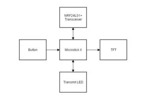
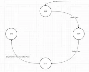
Base Station: The code behind our guns and base station follow two separate state machines. The base station starts in an idle state where nothing would happen until a button was pressed to transition the base station into a join state. In this state the base station would wait to receive join requests over the radio from the available guns. When a gun asks to join the base station, the base station checks its ID and adds it to an array of IDs to keep track of which gun is in the game. This helps prevent a gun from joining multiple times because the base station can check the gun’s ID against the array’s and ignore request messages if the gun is already in the game. This also allows for future scalability of the game as more players can join provided they have the proper gun hardware. After all of the players have entered the game, another button will be pressed on the base station to transition the base station into the play state, which would in turn send a signal over radio to all the guns that the game had started. In the play state, the base station will repeatedly receive updates from the guns with their current health. The base station is connected to a TFT display which will display the leftover health of all guns. If a gun loses all its health, the base station would end the game by sending a game over message to all the guns and transition to the end game state. This transition could also be achieved by pressing a button on the base station if a player wants to end the game early. In the end game state, the base station would decide which player won, based on who has the most lives remaining, and then display it on the TFT screen. To restart the game, one can simply press the button on the base station again which will return the base station to its idle stage.
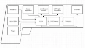
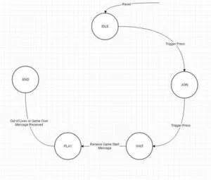
Gun: The guns also started in an idle state where they would do nothing until their triggers are pulled to transition to the join state. In the join state, the gun will repeatedly broadcast its ID in order to request to join the game. When the gun joins the game, the base station TFT will display its ID and health on the screen. Once the base station transitions to the play state, it will broadcast a message to the guns in the wait state and transition each gun to their individual play state. The gun’s speaker will emit a famous Duke Nukem line “Ready for action” to indicate to the players that the game has begun. In the play state, two protothreads are used, one for the gun and one for the radio. The gun thread will pulse the infrared emitter at a frequency of 38 kHz and the corresponding red “shoot” LED when the trigger is pulled, shooting the gun. A laser gun sound will also emit from the speaker to indicate the firing of a gun. Meanwhile, the thread will also check its own IR detector to see if the player has been hit by the other gun and would decrement player health if hit. If the player does get hit, a green “health” LED turns off to signal to the player and the speaker will also emit an “oww” sound. The gun would also be disabled for a few seconds to prevent the player from being repeatedly shot and taken advantage of. A series of LEDs displaying how much health the player has left is constantly being updated to decrement as the gun registers a hit. The radio thread will also repeatedly send out health information to the base station in order to keep track of live health. Once the gun loses all of its lives, it transitions to the end game state. In the end game state, the gun blinks an led to signal the game has ended and will emit the final end game sound through the speaker to indicate to the player. To restart the game, one simply has to turn off the gun and turn it on again by pressing the power switch.
Hardware Software Tradeoffs
Heads-up display: Originally instead of displaying the life LED on the gun itself, we planned to incorporate a series of LEDs onto a set of goggles and emulate a heads-up display. Figuring out a way to effectively mount the LEDs became an issue as it required long wires that could easily tangle up the player.
Radio: We decided to only send single bytes of data as our payload to simplify our code and because we did not need more than one byte. We turned auto-ACK off because multiple receivers would respond to the same message with an auto-ACK packet causing interference between them.
Sound: The way we generated our sound was by iterating through a list of voltage values going through a 4-bit DAC. We originally wanted a different timer for each sound because each sound should be generated at a different frequency in order to sound accurate. Instead of doing that, we used a single timer and set the timer property each time for sound generation risking slower overall code execution. We also had to aggressively use delays immediately after the sound in order to let the entire sound play which ran the risk of affecting our radio transmission.
IR Receiver/Emitter: The IR emitter had to be physically separated from the receiver by quite a distance on each gun in order to prevent suicidal gunshots as IR radiation can reflect from objects and hit the receiver on the same gun. This caused long wires on the solder board which took over already limited space.
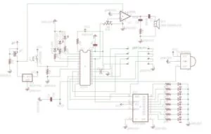
High Level Block Diagram
Hardware and Software
Radio
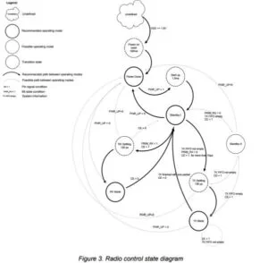
For our project one of the first things we worked on was using the nrf24l01+ chip to send and receive messages over radio. There were no libraries to use this with the PIC32 and the XC32 compiler, so we needed to create our own. We started by setting up an SPI connection to the radio where we could send arrays of characters to the radio and receive characters back which would be put into another array. Once this was done we wrote functions for transitioning between states in the radio. The radio has four main states as shown in the state diagram below. The radio starts in the power down state where registers can be read and written to and where it uses a smaller amount of power than in the other states. When PWR_UP is set high in the radio’s config register the radio transitions to the standby I state where it can still be written to and read from and can also transition from there to the RX mode and TX mode states. To transition to the RX mode state PRIM_RX must be set high in the radio’s config register and then the CE pin must be driven high. The radio will stay in this mode until CE goes low again and will then transition back to standby I. In the RX mode state the radio goes into a receive mode where it will receive packets and put them into a FIFO if the packet is valid. To put the radio in the TX mode state PIRM_RX must be set low and then CE must be driven high. In TX mode the radio will transmit all packets in the transmit FIFO and then transition to a standby II mode. In the standby II mode PWR_UP can be set low to go to the power down state or more packets can be put in the TX FIFO and the radio will go back into TX mode to send them.
Before setting the radio in either mode some setup has to be done by changing various options. The radio had an option for auto acknowledgement packets to be sent. It did this by having the transmitter send a packet and then automatically go into receive mode. When the receiver received a packet it would go into transmit mode and send the auto ack packet. The transmitter would detect the auto ack packet and trigger an interrupt that the original packet was sent correctly or would try retransmitting the packet if the auto ack packet wasn’t received and trigger an interrupt after a set amount of retries. We originally tried using this feature but it caused issues because both of our guns would try to send back auto ack packets causing interference so we needed to disable this and also set the radio’s automatic transmission retries to zero. Another option we needed to change was to set the payload width to 1 byte. We decided to structure our sent data to fit in this one byte by having the first two bits be the ID of a gun, the next two bits be a code for what the message is, and the final four bits be the payload of the message. An example packet might be 10100101 which would mean player two is sending a packet with a 10 code, which means the packet is sending the lives the gun has, and the final four bits (0101) say that the amount of lives is five. The last option that was relevant to us was setting the addresses for the transmit and receive pipes on the radio. We decided to use the default reset values on our project but if another group decided to use the same radio we did we might have needed to change the address to prevent us from receiving their packets by accident.
To transmit packets in our project we wrote a function that would start by flushing the TX FIFO in case any data was still in there. Next we would write the data to be sent by sending one byte at a time from an array of characters passed to the function over SPI where the most significant byte of data was sent first. When this was finished the function would block until the radio triggered an interrupt signalling the packet was successfully transmitted or that if auto ack was enabled the maximum amount of retransmissions occurred. The ISR for the radio simply reset the interrupt flag on the radio and set a flag high that could be used by the rest of our code. We could clear our flags in the function or they could be taken out and used as part of the main code’s logic. We opted to let the function clear our flags and assumed our transmissions would be sent. The radio could then be powered down and up to go back to the standby I state so it could go into TX mode or RX mode from there.
To receive packets we put the radio in TX mode and waited for an interrupt from the radio. In this ISR the received packet was put into an array of characters with the first byte in the array being the MSB of the data. After this a flag was set for use in the rest of our code and the interrupt was cleared from the radio. The rest of our code was able to use this receive flag to only do things after data was received and made it so we did not need to block when receiving. The array the data was written to could also be used when the code was ready to deal with the received data.
The radio had one pin for triggering all types of interrupts so our ISR had to first check what type of interrupt occurred by reading from a register in the radio and then clearing that register by writing a one to the appropriate bit, and then doing anything else that was necessary.
Base Station
The base station coordinated the game for all the guns and displayed information about the game. It used a state machine for its logic that had four states, idle, join, play, and end. In the idle state the game waited for a button to be pressed to start the game. It would display instructions saying, “press button to start” so a player would know what to do. When the button was pressed the base station transitioned to the join state.
The join state dealt with looking for players to join the game. The state started by displaying on the TFT screen that it was waiting for players. The base station then set the radio in RX mode and waited for guns to send packets with requests to join. When a request was received the packet id was checked to see what gun sent it. The ID was then compared to an array containing IDs of all players that had joined and if the ID was not in yet the gun was added to the ID array and the base station put that player’s health into another array and incremented the player count. At this point the gun successfully joined the game. The base station would display a list of all players and their healths on screen so players could tell if their gun successfully joined or not. The base station would wait for guns to join until the button was pressed. When the button was pressed the base station would transmit a start game message for all guns and transition to the play state.
The base station began the play state by displaying that the game had started on screen. In this state the base station would go into receive mode to check if guns were sending updates with their life count. If a packet was received the base station would check the ID, code, and payload to see if the packet was a player’s life, which player sent it, and how much life the player had. The base station would then update the life array with the player’s new life. The base station also checked how many players ran out of lives. If every player but one ran out of lives the base station would automatically end the game, otherwise the game could be ended early by pressing the button. The base station would also display the health of each player on screen in a list. When the game ended in either of the two ways the base station would send out an end game message, display the winner of the game based on who had the most lives left, and go to the end game state.
In the end game state the base station continued to transmit the end game message in case a gun did not receive it the first time and waited for the button to be pressed to restart the game. The game could also be restarted by turning the power off and on which was usually the better way to do it because the radio was only reset when it was turned off and on again. Pressing the button did attempt to reset all radio registers and base station variables however.
Guns
The guns like the base station also worked using a state machine containing five states idle, join, wait, play, and end. The radio also used two protothreads: one for the gun logic and one for the radio. The idle state waited for the player to press the trigger to transition to the join state. The idle state also turned on the green life LED to signal the the gun was on and in idle. The radio thread did nothing in the idle state.
In the join state guns attempted to join the game. The gun thread yielded to the radio thread in the join state. The radio thread worked by sending a message with the gun’s ID and the request to join code out to the base station. The thread also turned on the red shoot LED to signal that the gun was attempting to join the game. When the player saw that the gun joined the game successfully the trigger could be pressed to go to the wait state.
In the wait state the guns waited for the start game message to be sent. The gun thread did nothing again in this state and yielded to the radio thread. The radio thread started by setting the radio in receive mode. When it received a packet the gun would check if it had the start game code in it. If it did the gun initialized its lives and played a sound to signal a game start. If the packet was something else the gun would ignore it. The gun would also blink the shoot LED to let the player know that the gun joined successfully and was waiting for the game to start.
In the play state the gun played the laser tag game. The radio thread would periodically transmit the amount of lives the gun had. After each send the radio changed into receive mode and waited for a short time to check if an end game message was sent out. It would keep repeating this cycle. The gun thread would start by updating its display of lives on the line of LEDs on the gun. It would then check if the player was alive. A player would always be alive except for a few seconds after they were shot. Getting shot occurred when an IR detector detected an IR beam from the other gun and triggered an interrupt. In this interrupt the gun would set itself as not alive and decrement its lives. If the interrupt triggered again while a player was not alive, the interrupt would do nothing besides clear its flag. In the main code if the player was not alive the gun would turn off the life LED and play a sound indicating the player was shot and then yield for two seconds for a short delay. After this delay if the player still had lives remaining the code would bring the player back alive, turn back on the life LED, and play another sound. This process gave the player a few seconds of invincibility after being shot where they could not shoot or be shot. If the player had no lives remaining the gun would transition to the end state. If the player was alive during the play state the gun would poll to see if the trigger had been pressed. If it was pressed the gun would blink the shoot LED, play a shooting sound, and pulse the IR emitter to shoot an IR beam.
In the end state the gun would blink the shoot LED to signal that the game was over and would repeatedly send its lives to the base station in case a previous transmission was missed. At this point a reset button on the gun could be pressed that would the power off and on returning the gun to the idle state.
Shift Register
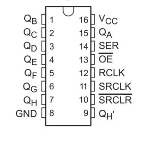
Since we need to display the player health using 8 LEDs, using 74HC5958 I/O pins on the PIC32 was simply not feasible. We solved the issue by simply incorporating an 8 bit shift register (), allowing control for up to 8 LEDs while only using a single SPI pin and two I/O pins on the PIC32. This is accomplished by converting the data we need to display from parallel to serial format via SPI. The PIC32 communicates with a shift register using serial information, and the shift register outputs information in a parallel format. In essence, every time the player was hit, the LED would decrement by one which we accomplished by sending out a serial data shifted logically by one in software. The 74HC595 is wired such that the SCK pin is used for the clock to time the data transfer, the RCK is used for for latching the bits, and the SER pin is used for the SPI data transfer. The clock sets the frequency that bits are shifted while the clock enable line allows the clock signal to propagate through to the shifting circuitry. A transition to low on the latch pin tells the shift register to save the current state of the 8 output pins connected to the LEDs. The SER pin on the shift register takes in an 8 bit serial data and outputs a single bit to each of the 8 LEDs in parallel, allowing full control of the LEDs. In terms of software design, we outputted the updated serial data by a logical shift and toggled the latch pin every time we needed to decrement the LED, eventually setting the latch pin to low to save the LED state.
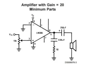
Audio Amplifier Circuit
Adding various sounds was not one of our original intentions, but it was rather a later addition to improve the overall user experience and help with debugging. We originally planned to have players wear earbuds connected to the CVREF output pin the PIC32. This way, we did not have to worry about sound amplification because the earbuds will have embedded audio amplification better than anything we can build on the breadboard. However, we soon realized that it was inconvenient to make players wear extra wires as this game requires high physicality and thus a player’s agility should not be impaired by long wires. On top of that, using a speaker would greatly enhance player experience and even spectator experience provided the sound was cool and accurate enough.
We tested the CVREF output voltage to be at around 0.5V, which was too low to drive an 8ohm, 0.25W speaker. We decided to employ the LM386 audio amplifier to amplify the signal and hopefully be able to drive the speaker to a loud enough volume. Since the sound we will be outputting do not need to be the best quality and the fact that we have very limited area on the solder board, we decided to implement an audio amplifier circuit using the least amount of hardware. The hardware we used included two capacitors, a 10K ohm trimpot, and a 10ohm resistor, which were enough to create a gain of 20 on the circuit. The LM386 would also be directly connected to the 6V battery pack, giving it the power it needs to amplify our sound.
In order to actually generate sound clips on the PIC32, we employed Bruce Land’s Matlab code on the 4760 website that converts a wav file into a list of voltage numbers. Since the CVREF is essentially a 4 bit DAC, the voltage values can therefore only range from 0 to 15, lowering the quality of the sound even further. The generated list would be stored as a header file and included at the beginning of our program. The way we generated sound was to open up a Timer 2 interrupt and set a time limit. Once timer 2 goes off, the program will iterate through the list and output the voltage values at a specific frequency based on the timer 2 limit through CVREF. We adjusted the timer 2 limit for each sound clip in order to create a an accurate representation of the sound by hopefully achieving the actual playback frequency. After each instance where we call for sound generation, we also yield time to another thread by a specific time amount catered for each sound clip so that we can make sure that each sound has been completely generated before moving on to other tasks. The implementation of fun sound effects and the addition of the onboard speaker greatly enhanced overall player experience as the player will know based on the sound effect when the game begins, when he/she shoots the gun, when a hit is registered, and when the game ends.
Results
Speed of Execution
Our design ended up working as intended. The speed of execution of our design was fast enough that a player would not notice any delay when pressing buttons on the base station or gun. When packets were sent between the guns and the base station results of the packet appeared on screen instantly to a human viewer. When a gun lost a life the base station updated the life count on the TFT fast enough that it looked instant. The switching between the radio and gun thread in the guns’ code was fast enough that polling for trigger presses did not delay anything for the player. Anytime the player pressed the trigger the gun would react without delay.
Reliability
Communication between the guns and the base station on the project was extremely reliable. Sometimes we sent repeat packets so the reliability was not an issue in those cases. In cases where only one packet was sent such as during the join state we did not have issues with packets not being sent. The radio also had a large range meaning players could move farther than 50 ft away and still send and receive packets successfully. Our radios had no radio interference with other people’s designs but if we did have this problem we could easily change our code to use different frequencies or pipe addresses to avoid this.
The IR emitters and detectors were mostly reliable in our final design. We only had one detector on each gun which was mounted on the top of the gun. This led to hits only being detected if the player aimed slightly above the gun rather than directly at the gun. Other than this the guns would detect hits reliably when the emitter was aiming within about a 10 degrees angle of the detector. The IR range was somewhat short and players could hit each other from about 35 ft away. The IR usually worked correctly but if the game was taking place in a noisy IR environment false hits could happen. Most places our guns were tested at had no problems with IR noise.
Usability
Our guns were designed to fit easily in an adult sized hand and had a comfortable weight to them from the hardware we attached. Children and people with smaller hands should still be able to use our guns even if they are slightly large. The TFT and various LEDs made it easy for the user to tell what state the guns and base station were in at anytime. They updated quickly so the user always had the most accurate information. The way the LEDs represented states was not immediately obvious but could be easily explained to a user. If a player tried using the guns in a game the function of the shoot and life LEDs were simple to understand as they turned on and off at the same time sounds were played. If a player pulled the trigger he or she would hear a laser shot sound and see a red LED blink making it easy to see that the gun was shot. Similarly when the player was hit the gun played a pain sound and turned off the green alive LED and turned off one the lives LEDs. This gave the player easy to understand feedback that he or she had been shot and lost a life.
Conclusions
Analysis and What We Would Do Differently
Our final design met most of our expectations. The code all worked the way we wanted it to with no glitches happening anywhere. We had hoped to originally have the guns work from about 60 ft apart but the IR emitter and detector we used did not have a long enough range and we were limited to 30 ft. The radio worked as expected and in the finished design we never failed to send packets correctly. Our sounds sounded good on our design and we could clearly hear a laser or pain sound when they played. The hardware worked correctly and all the LEDs turned on and off when they were supposed to and made it clear what the gun was doing at any given time. The TFT displayed players, scores, and information in a clear manner as we wanted it to. We had hoped to make a complete radio library during our project but had to make an incomplete one in the end due to time constraints. This had no negative impact on our final project in the end however.
If we were to do our project again we might try to complete the radio library to make it easier to integrate into our code. We would also try to have the join state in the game work in a more automated way by having the player just press one button to join. We would want to expand the scope of our game more so the software could handle more than four players if we built more guns. We would try to put more IR detectors on our guns for more reliable hit detection and use brighter IR LEDs.
Intellectual Property Considerations
Laser Tag games have been implemented since 1984, but our game does not copy any hardware or software from any of the current or past laser tag game producers as we arrived at our own game with unique software and hardware combinations. For the implementation of this project, we mostly used references from online technical documentations or materials from the ECE 4760 web page, namely the Matlab program that converts a Wav sound file to a list of 4 bit voltage values, the TFT library, the protothread library, and the example DMA code. We implemented our radio library for the nRF24L01+ as none currently exist currently for the PIC32. We do not own all the sound clips present in the project. The game start sound comes from Duke Nukem video game originally released for the MS_DOS in 1991. The laser gun sound and the pain sound comes from an open source sound clip library online. The game ending sound comes from the Pac-Man arcade game originally released in 1980. All sound has been heavily edited and converted from digital to analog in a format of a list of values. We do not plan on marketing our project for profit so we are not infringing on any sound copyrights. The project also does not infringe on any patent claims as all hardware and software configurations were developed independently by the group.
Ethical Considerations
Our project did not do anything that would be considered unsafe or environmentally unfriendly. Playing the game presents no health risks to either players or bystanders as we only use low-intensity IR beams and radio signals that comply with FCC standards. Our performance data claims in this report are honest and realistic and are supported by our testing and experiments from building and using our project. Working on this project helped us improve our technical competence through learning how to use our hardware and software. We properly credited everyone whose code we used in this project and properly credited all members of the team who worked on this project. We did not discriminate when making our team for this project based on gender, religion, sexual orientation, disability, age, national origin, gender identity gender expression, race. When building our project we did not injure anyone or steal anything during the process. We will release all our hardware and software from our project so it can assist colleagues and co-workers in their professional development. We do not intend for our project to cause any physical or psychological harm to any participants or bystanders. We hope that our project will inspire other similar projects that will cultivate a love for physical manifestation of past classic games.
Legal Considerations
FCC: To comply with the FCC regulations for low power non-licensed transmitters our transmissions must be in the 2.4-2.835 GHz frequency range and must fall under the emission limit of 50,000 µV/m @ 3 m. The RF transceiver we are using is the Nordic nRF24L01+ 2.4GHz Wireless Transceiver, which is an ultra low power (ULP) 2Mbps RF transceiver IC for the 2.4GHz ISM (Industrial, Scientific and Medical) band within compliance. Fred Kummer is also a licensed Technician-Class Radio Operator
Schematics
Source: Lazer Duel
- How many players can play the Lazer Duel game?
The implemented system supports two players, though the code can be expanded if more guns are built. - How does a gun register a hit?
When a gun emits a 38 kHz IR beam and another gun's IR detector senses that beam, the hit registers and the hit gun loses one life. - How does the base station know player health?
Each gun periodically sends its current health over the nRF24L01+ radio to the base station, which updates the TFT display. - What ends the game?
The game ends when a player reaches zero lives or when the base station operator presses the end button; the base station then signals all guns with a game over message. - How is sound generated on the guns?
Sound clips are produced by outputting 4-bit DAC values from CVREF via Timer 2 interrupts and amplified with an LM386 to drive a speaker. - Why was auto-ACK disabled on the radio?
Auto-ACK caused interference because multiple receivers would respond simultaneously, so it was disabled and retries set to zero. - How are the gun life LEDs driven?
An 8-bit 74HC595 shift register is used to control the eight life LEDs using SPI and two additional control pins. - What measures prevent repeated immediate hits?
After being hit, a gun becomes not alive for a few seconds (invincibility period) during which further IR interrupts do nothing; then the player is restored if lives remain. - Can the game be restarted without power cycling?
The base station can reset variables when the button is pressed, but full radio reset is best achieved by power cycling the device; guns restart by toggling power. - What is the range of the IR and radio?
Radio range exceeded 50 ft reliably; IR hit detection worked up to about 35 ft (roughly 10 meters) in testing, though project statement mentions gameplay within about 20 meters.