Summary of Lab 2: Basic digital input and output
This article explains how to read digital inputs from a push button switch using a PIC16F688 microcontroller. When the button connected to RC1 is pressed, it pulls the pin low, toggling an LED on RC0. The project utilizes a 10K pull-up resistor and software debouncing via the MikroC `Button` library to ensure stable readings.
Parts used in the Digital Input with Push Button Project:
- PIC16F688 microcontroller
- Push button switch
- LED
- 10K resistor
- MikroC compiler
Description
Today we will learn how to read digital inputs from a push button switch. A digital input has only two values: 1 and 0. The configuration of the push button switch is same as that of the reset switch except it goes to a different port pin. The status of the switch will be read through RC1 and every time when it is pressed, an LED connected to RC0 will be toggled ON and OFF.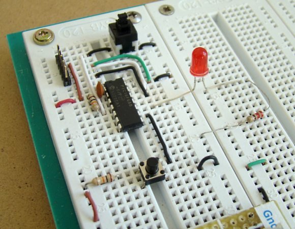
Required Theory
You must be familiar with the digital I/O ports of PIC16F688 and their direction settings. If you are not, read Digital I/O Ports in PIC16F688.
Circuit Diagram
To our last setup (see Lab 1: Flashing an LED), connect a push button switch to RC1 as shown below. The input ports of a PIC microcontroller have very high input impedance, and therefore, during normal condition when the switch is open, the RC1 pin is pulled ‘High’ through the external 10K resistor. When the switch is pressed, RC1 is pulled to ground and the microcontroller will read it as logic ‘Low’. In this way, a simple push button switch with a pull-up resistor can be used to provide digital inputs (1 and 0) to the microcontroller.
Software
Since the switch is connected to RC1, this port pin must be defined as input. This is done by setting the corresponding bit in the TRISC register. Again, don’t forget to disable the comparators and ADC channels. The code for this experiment is provided below. You should compile it with the MikroC compiler and load the output hex file inside the PICMicro. The MikroC compiler has an in-built library routine (named Button) for reading digital inputs from push button switches. The syntax is,
You can see that the Button command has debounce features built in. – See more at: 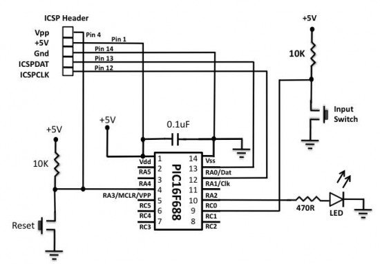
Debouncing a switchWhen a mechanical switch (like a push button) is pressed or released to make or break an electrical contact, the switch tends to make multiple transitions between ‘open’ and ‘close’ before coming to the stable final state. This is called switch bounce and this activity may go on for tens of milliseconds. We cannot see this bouncing but a microcontroller is relatively fast as compared to the action of the switch, and is, therefore, able to recognize this as multiple button presses and respond accordingly. Therefore, the switch must be debounced before it’s status is read by a microcontroller. Debouncing circuits require extra hardware and thus raises the cost of the embedded system. The easiest solution is to implement debouncing in software. The simplest logic is to wait for a few milliseconds (5-20 ms) after the key press or release is detected, and read the final state of the switch again to make sure it is a valid button press or release.
For more detail: Lab 2: Basic digital input and output
- How does the push button switch provide digital inputs?
The input ports have high impedance; when open, a 10K resistor pulls the pin High, and when pressed, the pin is pulled to ground for a Low reading. - What port pins are used for the switch and the LED?
The push button switch is connected to RC1 and the LED is connected to RC0. - Which register bit must be set to define the port pin as input?
The corresponding bit in the TRISC register must be set to define the pin as an input. - Why is debouncing necessary for mechanical switches?
Mechanical switches tend to make multiple transitions between open and close before stabilizing, which a fast microcontroller might interpret as multiple presses. - What is the easiest solution to implement debouncing?
The easiest solution is to implement debouncing in software by waiting a few milliseconds after detecting a key press or release. - Does the MikroC compiler have a built-in routine for this task?
Yes, the MikroC compiler has an in-built library routine named Button that includes debounce features. - What values does a digital input have?
A digital input has only two values: 1 and 0. - What happens if you do not disable comparators and ADC channels?
The text implies these must be disabled to properly configure the port pin for digital input, though specific consequences of not doing so are not detailed beyond the instruction.