Summary of IR Remote Control Repeater using PIC12F629
This article describes a PIC-based IR remote control repeater that receives IR signals and retransmits them using a generated 40 kHz (configurable to 38.4 kHz or 37 kHz) carrier with ~15% duty cycle. The firmware toggles an output at high speed within tight instruction-cycle constraints; GPIO5 selects between two frequencies and GPIO2 provides modulation input (typically from an IR decoder). The project notes IR LED wavelength compatibility (950 nm works; 875 nm failed on Sony gear) and provides source code, HEX files, and a schematic.
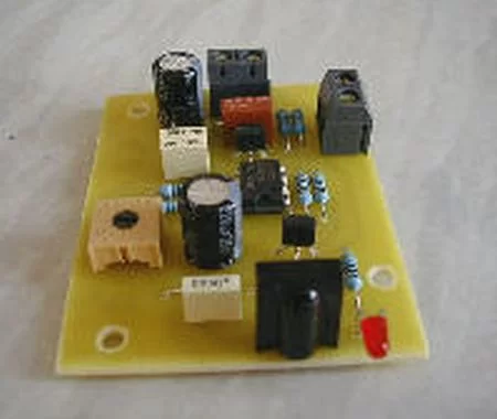
Parts used in the IR Remote Control Repeater:
- PIC microcontroller (12F629, 12F675, or 12F683)
- IR receiver module (standard remote IR detector)
- IR LED (950 nm, e.g., TSUS5400 or equivalent)
- Resistor(s) for LED current limiting
- Decoupling capacitor(s) for PIC supply
- Power supply (e.g., 5V regulated)
- Wiring/PCB or perfboard and connectors
- Optional IR decoder IC (provides modulation input to GPIO2)
This circuit receives the signal from a IR remote control, like those used to control your TV or DVD player and allows the signal to be repeated in another location.
To get a 40Khz carrier requires an output to be toggled on and off 40,000 times a second, which means the code needs to execute in 1,000,000/40,000 instruction cycles; this gives a very tight 25 instructions in which to do the job. Fortunately it’s an easy job to do so most of the instructions are just used to waste cycles. It’s not easy to get an accurate frequency with so little time and few instructions cycles to play with but the IR receivers will work several Khz either side of their design detection frequency so it’s not a problem.
This code can generate a 40Khz, 38.4Khz or 37Khz carrier with a ~15% duty cycle. The frequencies are configurable in the source code such that once programmed GPIO5 input on the PIC allows the selection of two frequencies. By default the code is set to produce 40Khz and 37Khz carriers which are modulated by the logic level on GPIO2. This would generally be connected to a IR decoder IC.
One thing I did find with the Sony equipment (I haven’t tested it with anything else), 875nM IR LEDs don’t seem to work, but the 950nM one specified works well. (TSUS5400, Mfg Vishay. Available from Farnell, part number 178302)
- Source Code (supports 12F629, 12F675, 12F683 21/06/2009)
- Hex (right-click Save As) for 12F675 / 12F629.
- Hex (right-click Save As) for 12F683
- Schematic
For more detail: IR Remote Control Repeater using PIC12F629
- What carrier frequencies can the code generate?
The code can generate 40 kHz, 38.4 kHz, or 37 kHz carriers with ~15% duty cycle. - How is the carrier frequency selected on the device?
GPIO5 input on the PIC allows selection between two configured frequencies. - What input provides the modulation signal to the transmitter?
GPIO2 provides the modulation input and would generally be connected to an IR decoder IC. - Which PIC models are supported by the source code?
The source supports PIC12F629, 12F675, and 12F683. - Does the project provide firmware and schematic files?
Yes, the article provides source code, HEX files for the PICs, and a schematic. - Are all IR LEDs compatible with this repeater?
No; 875 nm LEDs did not work with Sony equipment, while 950 nm LEDs (e.g., TSUS5400) worked well. - Why is generating 40 kHz challenging in firmware?
Generating 40 kHz requires toggling an output 40,000 times per second, leaving only about 25 instruction cycles per toggle for the PIC code, so timing is tight. - Can the IR receivers tolerate slight frequency offsets?
Yes, IR receivers will work several kHz either side of their design detection frequency, so slight frequency inaccuracies are acceptable.