Summary of PIC12F675 microcontroller as Flip Flop
This article details using a PIC12F675 microcontroller to emulate D-type and JK-type flip-flops. The D-type implementation uses edge-triggered and port-change interrupts, featuring negative edge triggering with active-low Set/Reset inputs. The modified JK version adds a unique feature: after reset, the logic level on GPIO5 determines whether the clock triggers on a positive or negative edge, eliminating the need for external pull-up resistors via internal weak pull-ups.
Parts used in the PIC12F675 Flip Flop Project:
- PIC12F675 microcontroller
- D-type flip flop configuration
- JK-type flip flop configuration
- Edge triggered interrupts
- Port change status interrupts
- Active low Set input
- Active low Reset input
- GPIO5 pin (Pin 2)
- Internal weak pull-up resistor
Code to make a 12F675 operate as a D-type or JK-type flip flop
Since I implemented a D type flip flop using the PIC Logic Elements I thought I might go the other way and implement an entire D type flip flop in a single PIC. This uses the edge triggered and port change status interrupts and was an opportunity to have a play with interrupts on the PIC.
As written this code will cause a PIC to function as a negative edge triggered D type flip flop with active low Set and Reset inputs.
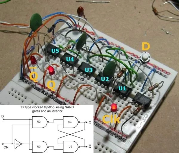
‘D’ type flip flop
- Source Code
- Hex (right-click Save As)
- Schematic PNG , PDF
Following the D type flip flop I’ve hacked it round to make a JK flip flop. This implementation has one extra ‘feature’ that a normal discrete logic device doesn’t have. After a reset, port GPIO5 (pin 2) is read and the logic level used to select either a positive or negative clock edge.
GPIO5 = 1, negative edge (GPIO5 uses weak pull-up, so no external resistor is needed)
GPIO5 = 0, positive edge
For more detail: PIC12F675 microcontroller as Flip Flop
- How does the code make the PIC function?
The code causes the PIC to function as a negative edge triggered D type flip flop with active low Set and Reset inputs. - Can the PIC be configured as a JK flip flop?
Yes, the author hacked the D type code to implement a JK flip flop. - What determines the clock edge selection in the JK version?
After a reset, the logic level read from port GPIO5 selects either a positive or negative clock edge. - Does the GPIO5 pin require an external resistor?
No, because GPIO5 uses a weak pull-up, no external resistor is needed. - What interrupt types are utilized in this project?
The implementation uses edge triggered and port change status interrupts. - What happens when GPIO5 is set to 1?
When GPIO5 equals 1, the device operates on a negative edge trigger. - What happens when GPIO5 is set to 0?
When GPIO5 equals 0, the device operates on a positive edge trigger. - Is there a difference between discrete logic and this implementation?
Yes, this implementation has the extra feature of reading GPIO5 to select the clock edge after a reset.