Summary of Internal Oscillator Recalibration Utility for PIC12F629
This article describes a utility circuit and software to recalibrate the internal 4MHz oscillator of PIC12F629 and PIC12F675 microcontrollers if their factory calibration data is lost. The system uses the AC utility supply frequency (50Hz or 60Hz) as a reference via a transformer to adjust the OSCCAL register, ensuring accuracy within 1%. It includes instructions for hardware construction, code implementation using a CALL instruction at address 0x3FF, and notes on using PICkit 2 programmers for automated updates.
Parts used in the Internal Oscillator Recalibration Utility:
- PIC12F629 microcontroller
- PIC12F675 microcontroller
- Transformer or Wall Wart (6 to 12 volt RMS AC output)
- Strip board or pad board
- Solderless breadboard
- PICkit 2 programmer (version 2.50 or later)
Description
The PIC 12F629 and 12F675 come equipped with an internal 4MHz oscillator, eliminating the need for an external crystal or RC network. This feature not only frees up one or two pins for I/O purposes but also facilitates integration into designs with minimal component counts.
The internal oscillator needs to be calibrated and this is achieved by reading a factory programmed calibration setting and writing it into the OSCCAL register during initialisation of the device by the application software.
The calibration word is located at the last address in the user program memory area, address 0x3FF. It is in the form of a RETLW instruction and the user code should include a CALL 0x3FF instruction which will return with the calibration setting in the W register. This can then be written into the OSSCAL register.
Problems arise if by accident or otherwise, the program memory at address 0x3FF is erased or over written. Since the calibration value is unique to each individual PIC there is no way to know what it was, but it is possible to recover it by recalibrating against a known frequency.
That’s where this software and circuit come into their own. Load a PIC with the code on this page and drop it into the circuit described here and within a couple of seconds it will provide a new calibration value to ensure the internal oscillator runs within 1% of 4Mhz.
PICkit 2 update
If you have a PICkit 2 programmer, get version 2.50 (or later) software from the Microchip website. This includes a menu option to recalibrate and reprogram the OSSCAL setting in one operation. This project page remains here for those who don’t have access to a PICkit2.
How it works
In order to calibrate the internal oscillator a known reference frequency is needed. Fortunately we don’t need signal generators or calibrated test equipment for this. In fact an accurate reference is available from the AC utility electric supply. In most parts of the World the utility electricity supply is generated at a frequency of either 50 or 60Hz (many digital clocks take advantage of this fact to keep time)
Using almost any transformer (or Wall Wart) with a 6 to 12 volt RMS AC output we can obtain an accurate reference source to calibrate the PICs oscillator against.
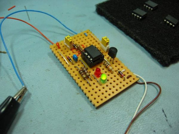
Schematics, Construction, and Code
So let’s get on with it. Construct the circuit shown below using a piece of strip or pad board, or just hook it up on a solderless breadboard.
For more detail: Internal Oscillator Recalibration Utility for PIC12F629
- How can the internal oscillator be calibrated?
The calibration word must be read from address 0x3FF and written into the OSCCAL register during device initialization. - What happens if the program memory at address 0x3FF is erased?
The unique calibration value is lost, but it can be recovered by recalibrating against a known frequency using this utility. - Can this project work without a signal generator?
Yes, an accurate reference source is available from the AC utility electric supply which generates 50Hz or 60Hz. - What type of transformer is required for the circuit?
Almost any transformer or Wall Wart with a 6 to 12 volt RMS AC output can be used. - How long does it take to get a new calibration value?
Loading the code and dropping the PIC into the circuit provides a new calibration value within a couple of seconds. - Does the updated PICkit 2 software offer a specific feature for this?
Version 2.50 or later includes a menu option to recalibrate and reprogram the OSSCAL setting in one operation. - What is the target accuracy after recalibration?
The process ensures the internal oscillator runs within 1% of 4MHz. - Where is the calibration word located in user program memory?
The calibration word is located at the last address in the user program memory area, which is address 0x3FF.