Summary of Interfacing with a Secure Digital (SD) card using pic-microcontroller
This article describes a lab project interfacing a Microchip PIC18F4520 microcontroller with a 2GB Apacer SD card using SPI mode. It covers hardware setup, including powering the SD card at 3.3V with pull-up resistors and using a more robust SD card holder. Software involved includes modified CCS v4.081 library drivers and example application code adapted to the PIC18F4520, enabling read/write access to SD card memory via RS-232 serial communication from a PC terminal. Limitations of memory addressing and lack of full FAT file system support due to hardware constraints are noted, with potential future improvements outlined.
Parts used in the SD Card Interfacing Project:
- Microchip PIC18F4520 microcontroller
- Apacer 2GB Secure Digital (SD) card
- HR845CT-ND SD card holder
- Strip of square-pinned header
- Bench top power supply (3.3 VDC output)
- 50 kΩ pull-up resistors
- RS-232 serial cable
- Personal computer with terminal emulator software
Overview
Secure Digital Cards, or SD cards, are used to hold information in many common electronic devices from digital cameras to mobile phones and come in sizes as small as 4 MB and as large as 8 GB. In this lab, we will establish communication between a Microchip PIC 18F4520 and a 2GB SD card manufactured by Apacer.
SD cards can operate three different communication modes: One-bit SD mode, four-bit SD mode, and SPI mode. SPI is a more basic protocol and it is widely supported by many microcontrollers, including the PIC 18F4520. We’ll be using SPI mode in this lab.
Hardware
Card Interface
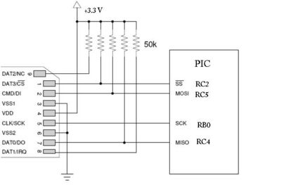
An SD card has 9 pins. Only 7 of these pins are used to communicate with an SD card in SPI mode. SD cards require between 2 and 3.6 VDC. In this lab, we use a bench top power supply to provide 3.3 VDC to both the PIC and to the SD card. 50k pull-up resistors are essential, even for the pins that are not being used for SPI communications. Note that a pull-up resistor should not be used on the clock line.

SD Card Holder
SD card holders are typically surface-mount components that are designed to be placed on printed circuit boards by machines. As such, they can be very difficult to handle and connect. At first, we were given an HR8464CT-ND SD card holder. Attempts to solder solid-core to the pins of this device caused the pins to fall out. Instead, we used an HR845CT-ND which had pins that were more resistant to axial force and thus easier to solder.
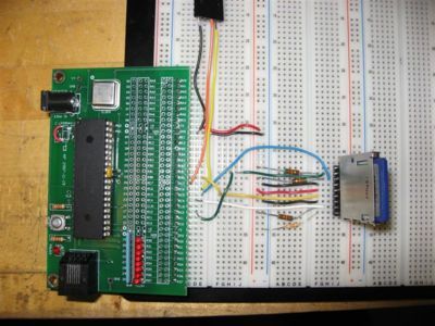
For this lab, we cut a strip of square-pinned header to the proper length and simply soldered the pins of the holder to it. See the photograph below for more detail.
Completed Circuit
Note that the PIC is being powered from a bench top power supply and that it is hooked up to a PC via the RS-232 cable provided in lab.
Software
Driver
Note that this lab was completed by making slight modifications to an example application included in the CCS v4.081 library. The low level driver code, included in the Drivers directory of the CCS installation, must be copied verbatim into the same directory as the application code.
Application
The original, unmodified application code was included in the newer version of CCS mentioned above. Note that as of Winter Quarter 2009, these drivers are not available in the Mechatronics lab but are available on the installation media provided in our lab kits. Modifications were made to the code to change the assignment of the SPI pins, tailor the preprocessor directives to use our PIC, properly configure RS232 and set the main clock frequency. Additional modification was made to make the application display the contents of the SD card identification register on startup. All modifications contain “MODIFIED” in their comments.
/////////////////////////////////////////////////////////////////////////
////                      ex_mmcsd.c                                 ////
////                                                                 ////
//// Similar to ex_extee.c, an example that demonstrates             ////
//// writing and reading to an MMC/SD card.                          ////
////                                                                 ////
/////////////////////////////////////////////////////////////////////////
////        (C) Copyright 2007 Custom Computer Services              ////
//// This source code may only be used by licensed users of the CCS  ////
//// C compiler.  This source code may only be distributed to other  ////
//// licensed users of the CCS C compiler.  No other use,            ////
//// reproduction or distribution is permitted without written       ////
//// permission.  Derivative programs created using this software    ////
//// in object code form are not restricted in any way.              ////
////                                                                 ////
//// Modifications for ME333 Winter 2009 Lab 5 by                    ////
////      Colleen Fryer, Sean Wood, and Mat Kotowsky                 ////
////                                                                 ////
/////////////////////////////////////////////////////////////////////////

 //These settings are for the CCS PICEEC development kit which contains
 //an MMC/SD connector.
 #include <18f4520.h>                // MODIFIED
 #fuses HS,NOLVP,NOWDT,NOPROTECT     // MODIFIED
 #use delay(clock=40000000)          // MODIFIED
 #use rs232(baud=19200, UART1)       // MODIFIED hardware UART uses  RC6/TX and RC7/RX

 #include <stdlib.h> // for atoi32

 //media library, a compatable media library is required for FAT.
 #use fast_io(c)
 #define MMCSD_PIN_SCL     PIN_B0 //o MODIFIED  THIS WAS A HUGE PROBLEM, C3 DIDN'T WORK
 #define MMCSD_PIN_SDI     PIN_C4 //i
 #define MMCSD_PIN_SDO     PIN_C5 //o
 #define MMCSD_PIN_SELECT  PIN_C2 //o
 #include <mmcsd.c>

 #include <input.c>

 void main(void)
 {
  BYTE value, cmd;
  int32 address;
  printf("\r\n\nex_mmcsd.c\r\n\n");
  printf("\r\n\n");

  if (mmcsd_init())
  {
     printf("Could not init the MMC/SD!!!!");
     while(TRUE);
  }
  mmcsd_print_cid();     // MODIFIED

  do {
     do {
        printf("\r\nRead or Write: ");
        cmd=getc();
        cmd=toupper(cmd);
        putc(cmd);
     } while ( (cmd!='R') && (cmd!='W') );
     printf("\n\rLocation: ");
     address = gethex();
     address = (address<<8)+gethex();
     if(cmd=='R')
     {
        mmcsd_read_byte(address, &value);
        printf("\r\nValue: %X\r\n", value);
     }
     if(cmd=='W') {
        printf("\r\nNew value: ");
        value = gethex();
        printf("\n\r");
        mmcsd_write_byte(address, value);
        mmcsd_flush_buffer();
     }
  } while (TRUE);
}
Operation
Interacting with the SD card is done via a PC connected by RS-232 to the PIC. Any terminal emulator can be used to connect to the correct COM port at 19200 baud. Once connected, powering up or resetting the system will cause the PIC to communicate with a card. If there is an error and the PIC can’t connect, the program will report an error message and quit. If it is successful in initializing communication with the card, it will immediately print the contents of the SD card’s identification register, then prompt the user to read or write to a given memory address.

The user can select whether to read or write by pressing R or W at the prompt. The user then selects a 16-bit memory address by entering 4 hexadecimal integers. After 4 integers are typed, the program will display the one byte of data at the given memory location or will prompt the user to enter data, depending on if read or write has been selected. If write has been selected, the user can enter two hexadecimal integers. After they are entered, the PIC will write out the value to the SD card at the specified memory location. The user is then returned to the read/write prompt.
Future Work
Though this lab demonstrated the ability to read and write to an SD card, there are a few improvements that can be made.
File System
The CCS v4.081 library does provide a driver to create and manipulate a FAT-16 filesystem on an SD card. The driver assumes the use of a PIC18F67J60 microcontroller which has 128 KB of program memory and 3808 bytes of RAM. Unfortunately, the PIC that we’re using in this lab, the PIC18F4520 only has 32 KB of program memory and 1536 bytes of RAM. This smaller amount of RAM proves to be insufficient to run the filesystem driver designed for the more powerful PIC. It is possible that the driver can be modified such that it would run on the 18F4520 should the required RAM overhead be decreased.
Capacity Availability
For ultimate simplicity, this application allows the user to provide a 2-byte memory address and enter one byte into that address. That amounts to 64 KB of total memory — considerably less than the 2 GB of memory the SD card is purported to have. This is because the example program only reads and writes bytes of memory from specific 16-bit addresses. In reality, the SD card stores data not in single bytes but in 512-byte blocks, and the driver assumes a 32-bit address space, not a 16-bit address space. In order to realize the full capacity of the SD card, one must read and write entire 512-byte buffers and use most of the 32-bit address space. This allows for total theoretical capacity of 2 TB, though no SD cards of this capacity currently exist (as of early 2009).

