Have you ever wondered how your PC and phones keep track of time even when the device is turned OFF? Well there is a Real Time Clock (RTC) that is kept powered even is the device is turned OFF. Once the device is turned ON and connected to the internet the device connects to a NTP server (Network Time Protocol) and updates the time and date. This post is intended to give a little insight over these RTCs and their interface with mid-range 8-bit microcontollers with I2C interface. It is possible to define a software I2C library if your favorite controller does not have a I2C bus, but that is beyond the scope of this post. This post will walk you through the steps involved in interfacing RTC with microcontroller.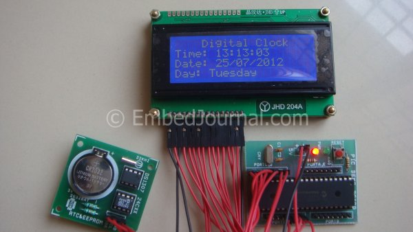
What are we looking at?
This how the competed project will look like (at lest mine did) once you have gone through the entire post The LCD display is a standard 20 character 4 line module. Asides that I have a MCU section on the right and the RTC and EEPROM breakout board with a CMOS battery on the left. You don’t have to have a module to get started with you can make the circuit connection on a GP board or on a breadboard. Here is a schematic of the DS1307, as for the PIC schematic I leave it to you to make your own schematic.
I have chosen PIC18f4520 as my controller because of it availability and features. But that doesn’t mean this document is restricted only to the interfacing RTC with this MCU only. If you are a PIC user then you are way off most of the code can be reused with minor modification. If you prefer using other families of controller (and good with it) you should be able to port the code to your own controller. If everything goes as intended by the end of this post you should be able to interface the RTC with any microcontroller of you choice.
The most common RTC that is available on the market is the DS1307 and its has been around for quite some time and hence there is an abundance of documentation online for its interface. The device can be interface using the I2C protocol also called as the two wire interface. This simple protocol that allows data to be read and written serially using just two line (SCL – clock and SDA – data).
I assume that readers are aware of the I2C protocol specifications if not please read my previous post here. The process of Interfacing RTC may turn out to be a little daunting if you don’t fully understanding the I2C bus specification. The datasheet of the DS1307 real time clock is quiet self explanatory and little has to be explained if you have a basic idea about the interface. There are a few time keeping registers in the IC that can be read and written. Once the actual time is set the clock will keep a track of the time. For this a dedicated power supply (CMOS battery) which kicks in if the power to the system is turned OFF.
The Time Keepers:
This is the list of the registers that you will have to configure and set for the RTC to work. This is a snapshot from the datasheet for your convenience. There are six registers for time keeping purpose and one register at 07h which is for configuring a square wave output derived from the clock. For simplicity we will leave that register for now, but this feature can be very useful I can think of a handful of application for it. Maybe you should too. For now we will stick to just the time
The column function tells you what function each register is going. Most of the details such a second minutes hours months and years are given in 4-bit BCD format. If the detail is less than 9 for example the tens place of the minutes and seconds can never go beyond 5. So instead of using a 4-bit format they have adopted a 3-bit format of BCD that can go up to 7. Similarly the tens place of the months is never going to go beyond 1 so it just a single bit saying 0 or 1. The registers bits that are marked 0 will always be read 0.
Next comes the representation of the time, either in 12-hour format or 10-hour format. This is done by the bit 6 of the hours register. If set the clock is in 12-hours mode and if cleared it is in 24-hour mode. In 24-hour mode the bit 5 will be used along with the bit 4 to read the tens digit hours (as it can go up to 2). In the 12-hours mode the bit 5 is used as a AM or PM indicator. If the bit is set then the time is in PM and if it is cleared it is in AM mode. And as shown in the table only bit 4 is used to display the tens digit of the hours.
Lastly there is a bit named CH (Clock Halt) in the seconds register. This bit when set will halt the time keeping process. Some applications may not require the time keeping operation to be going on forever. For example a system that is connected to a network operator (GSM) or a device connected to the internet can get its time stamp from a NTP server. So the programmer has the ability to shut down the time keeping process when not needed thereby reducing the operational current.
For more detail: Interfacing RTC with Microcontroller