Summary of Interfacing PIC16F84A with SD card
This article details interfacing a 2 GB micro SD card with a PIC16F84A microcontroller using software SPI and UART. Since the PIC16F84A lacks hardware SPI and UART modules, the project utilizes software implementations to read raw data from the SD card without requiring a file system or high memory capacity. The system uses an AMS1117 regulator for voltage conversion and a MAX232 chip for PC communication, reading data byte-by-byte due to limited RAM.
Parts used in the Interfacing SD card with PIC16F84A:
- PIC16F84A microcontroller
- 8 MHz crystal
- 2 x 22pF ceramic capacitors
- SD Card
- AMS1117 3.3V voltage regulator
- 3 x 3.3K ohm resistor
- 3 x 2.2K ohm resistor
- 2 x 10K ohm resistor
- 5 x 10uF polarized capacitor
- 100nF ceramic capacitor
- MAX232 chip
- Female RS232 connector
- Male-female RS232 cable
- 5V Power source
- Breadboard
- Jumper wires
This topic shows a simple interfacing of 2 GB micro SD card with PIC16F84A microcontroller.
I used the PIC16F84A to read the SD card raw data which doesn’t require a microcontroller with high RAM or ROM. In this interfacing I used software SPI because the PIC16F84A doesn’t have a built-in hardware SPI module.
In this example there is no need for file systems (FAT16, FAT32 …) because we’re dealing with raw data which stored in the SD card memory spaces.
CCS IDE serial monitor is used to display the data after reading it and here the UART protocol is used. I used software UART because the PIC16F84A also does not have a UART module.
the link below shows a small PIC16F84A MCU UART example:
Software UART for PIC16F84A microcontroller
In this project I used the MMC/SD card driver for CCS C compiler which is described in the post at the link below:
MMC/SD Card driver for CCS PIC C compiler
The PIC16F84A MCU has only 68 bytes of data RAM which means that it is not possible to load an entire sector of 512 bytes, but we can read many sectors byte by byte.
Hardware Required:
- PIC16F84A microcontroller
- 8 MHz crystal
- 2 x 22pF ceramic capacitors
- SD Card
- AMS1117 3.3V voltage regulator
- 3 x 3.3K ohm resistor
- 3 x 2.2K ohm resistor
- 2 x 10K ohm resistor
- 5 x 10uF polarized capacitor
- 100nF ceramic capacitor
- MAX232 chip
- Female RS232 connector
- Male-female RS232 cable
- 5V Power source
- Breadboard
- Jumper wires
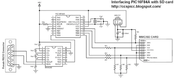
Interfacing SD card with PIC16F84A MCU circuit:
The AMS1117 3.3V voltage regulator is used to supply the SD card with 3.3V. Also, 3 voltage dividers are used to step down the 5V which comes from the microcontroller to about 3V which is sufficient for the SD card. Each voltage divider consists of 2K2 and 3K3 resistors.
The MISO of the SD card is connected directly to the microcontroller.
MAX232 integrated circuit is used to interface the microcontroller with the PC, I connected just one wire (RB3) because I need to transmit data from the SD card to the microcontroller and then from the microcontroller to the PC, there is no need to connect the second wire because I don’t have to send data from the PC to the microcontroller.
In this project the PIC16F84A MCU runs with 8MHz crystal oscillator.
SD Card raw data read using PIC16F84A CCS C code:
The C code below was tested with CCS PIC C compiler version 5.051.
Software SPI is used to interface the MCU with the SD card with 4 data lines: SDI, SDO, SCL and CS.
The code below reads the SD card sector 0, sector size is 512 bytes. To be able to read the whole sector I used the function sdcard_read_byte which allows me to read any byte located in the SD card. For example the function sdcard_read_byte(200, &value); reads the byte of address 200 and saves its data (1 byte) in the variable pointer value.
The functions sdcard_init and sdcard_read_byte return 0 if OK, non-zero if error.
Complete C code is below.
Read more: Interfacing PIC16F84A with SD card
- Why is software SPI used in this project?
Software SPI is used because the PIC16F84A does not have a built-in hardware SPI module. - Does this project require a file system like FAT16 or FAT32?
No, there is no need for file systems because the project deals with raw data stored in the SD card memory spaces. - How is the data displayed after reading it from the SD card?
The CCS IDE serial monitor is used to display the data, utilizing the UART protocol. - Can the entire sector of 512 bytes be loaded into the PIC16F84A memory at once?
No, the PIC16F84A has only 68 bytes of data RAM, so sectors must be read byte by byte. - What component is used to supply the SD card with 3.3V?
The AMS1117 3.3V voltage regulator is used to supply the SD card with 3.3V. - How are the voltage dividers constructed for the SD card interface?
Each voltage divider consists of a 2K2 and a 3K3 resistor to step down the 5V from the microcontroller to about 3V. - How many wires are connected between the MAX232 and the microcontroller?
Just one wire (RB3) is connected because data transmission is only needed from the SD card to the PC. - What frequency oscillator does the PIC16F84A run with in this project?
The PIC16F84A MCU runs with an 8MHz crystal oscillator.