Summary of Interfacing Matrix Keypad with PIC Microcontroller
This article explains what a matrix keypad is and how to interface a 4x4 matrix keypad with a PIC microcontroller using scanning. It describes arranging keys in rows and columns to reduce I/O pins, the scanning method (drive columns, read rows), and an example showing a 4x4 keypad connected to PORTB (RB0–RB3 as outputs for columns, RB4–RB7 as inputs for rows) with results shown on a seven-segment display. VDD and VSS should be tied to +5V and GND.
Parts used in the Matrix Keypad with PIC Microcontroller:
- 4x4 Matrix Keypad
- PIC Microcontroller
- Seven Segment Display
- Connection wires
- Power supply (+5V and GND)
This tutorial explains ‘What is a Matrix Keypad ?’ and ‘How to Interface Matrix Keypad with PIC Microcontroller ?’.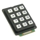
Matrix Keypad
Matrix Keypad is a very useful and userfriendly when we want to design certain applications like Calculator, Telephone etc. Matrix Keypad is made by arranging push button switches in rows and columns. Just imagine, if you want to interface a 4*4 (16 keys) matrix keypad with a microcontroller. In the straight forward way, you will need 16 pins of a microcontroller for that, but by using a simple technique we can reduce it to 8 pins. In the matrix keypad switches are connected in a special manner a shown in the figure below.
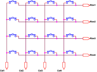
Pressed keys can be detected by Scanning. For the sake of explanation, lets assume all column connections (Col1 – Col4) are input pins and all row connections (Row1 – Row4) are output pins. In the normal case (not scanning) all column inputs where in LOW (GND) state. For scanning keypad,
- A Logic HIGH signal is given to Col1 of column inputs.
- Then each Row output (row1 – row4) is scanned one by one. If any of the key belongs to first column is pressed, the Logic high signal from the Col1 will pass to that row. Through we can detect the key.
- This process is repeated for all columns if we want to detect multiple keys.
In this post I am explaining only about detecting one key at a time. For explaining the working I am using a 4*4 matrix keypad and the result is displayed in a Seven Segment Display. Matrix Keypad scanning is stopped as soon as any key press is detected and the Scanning is restarted if we need more inputs.
Interfacing with PIC Microcontroller
Matrix Keypad can also be interfaced with PIC Microcontroller using MikroC Libraries.
Circuit Diagram
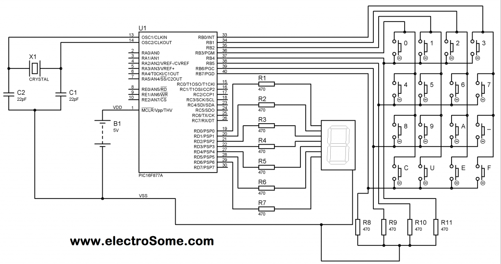
Note: VDD and VSS of the pic microcontroller is not shown in the circuit diagram. VDD should be connected to +5V and VSS to GND.
Matrix Keypad is connected to the PORTB of the PIC Microcontroller. Each column of the Matrix Keypad is connected to RB0 – RB3 of the PIC Microcontroller, which are configured as output pins. While each row of the Matrix Keypad is connected to RB4 – RB7 of the PIC Microcontroller, which are configured as input pins.
For more detail: Interfacing Matrix Keypad with PIC Microcontroller
- What is a matrix keypad?
A keypad made by arranging pushbutton switches in rows and columns to reduce required microcontroller pins. - How does scanning detect a pressed key?
A column is driven HIGH and each row is read; if a row reads HIGH the corresponding key in that column is pressed. - How many pins are needed for a 4x4 keypad using matrix arrangement?
Eight pins (four for columns and four for rows) instead of sixteen. - Which PORT and pins of the PIC are used in the example?
PORTB: RB0–RB3 for columns and RB4–RB7 for rows. - Are column pins inputs or outputs in the explained scanning method?
Columns are configured as output pins (driven HIGH during scanning). - Are row pins inputs or outputs in the explained scanning method?
Rows are configured as input pins to detect the driven HIGH. - Does the tutorial show how to display the result?
Yes, the detected key result is displayed on a seven segment display in the example. - What should VDD and VSS of the PIC be connected to?
VDD should be connected to +5V and VSS to GND.