
Summary of Test Ideas: Protect USB measurement circuits
USB data-acquisition modules are cost-effective and simple for manufacturing tests but can be damaged by faults in devices under test (DUT). Typical USB DIO modules use 8-bit bidirectional tristate ports; one pin drives the circuit while another reads its response. Faults like shorts to ground, VCC, or higher voltages on the DUT can expose the module's input to damaging voltages (for example through a short across a 2-kΩ resistor to +15 V). Adding protection circuits between the DUT and the USB module prevents such damage.
Parts used in the USB data-acquisition protection project:
- USB data-acquisition module with 8-bit bidirectional tristate ports
- Digital output pin (from USB module)
- Digital input pin (from USB module)
- Device under test (DUT) circuit
- 2 kΩ resistor (from collector to +15 V supply)
- +15 V supply
- Protection circuitry (unspecified protective components placed between DUT and USB module)
USB data-acquisition modules offer good value and ease of use, which makes them an attractive choice for manufacturing test. But before you use the modules in a manufacturing test system, you need to take steps to protect them. During manufacturing test of circuit boards or subassemblies, a defect in an assembly may result in a condition that damages a data-acquisition module.
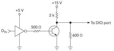
The typical USB DIO (digital I/O) module uses a set of 8-bit bidirectional tristate ports. Figure 1 shows a typical circuit that we test with one of those ports. We use one digital output pin from the USB module to drive the circuit and one digital input pin to read the circuit’s response. If the circuit works properly, we expect to see a clean digital signal from the circuit. For a circuit coming off the manufacturing line, however, the digital input pin of the DUT (device under test) could be shorted to ground, shorted to VCC, or shorted through some low impedance to a higher voltage. Any of these conditions can damage the USB module’s input pin.
If there’s a short across the 2-k resistor from the collector to the +15-V supply, that voltage will appear at the USB module’s input pin, which could damage it. To avoid such damage, we add protection circuits between the DUT and the USB module.
For more detail: Test Ideas: Protect USB measurement circuits
- Why do USB data-acquisition modules need protection in manufacturing test?
Because DUT faults such as shorts to ground, VCC, or higher voltages can expose the module input to damaging voltages. - What kind of ports do typical USB DIO modules use?
They use 8-bit bidirectional tristate ports. - How is the USB module typically connected to the circuit under test?
One digital output pin drives the circuit and one digital input pin reads the circuit's response. - What DUT fault examples can damage the USB module input?
Shorts of the DUT input pin to ground, to VCC, or through a low impedance to a higher voltage can cause damage. - How can a short across the 2 kΩ resistor cause damage?
If the resistor from the collector to the +15 V supply is shorted, +15 V can appear at the USB module input and potentially damage it. - What general measure is recommended to protect the USB module?
Add protection circuits between the DUT and the USB module.
