
Summary of Interfacing 7-Segment Display With PIC Microcontroller – MikroC
Summary (under 100 words): A 7-segment display uses seven LED segments (plus optional decimal point) to show digits 0–9 and limited letters. Segments are labeled a–g; different combinations light specific segments to form characters. Displays come as common-anode (anodes tied together, segments grounded to turn on) or common-cathode (cathodes tied, segments driven high to turn on). Each segment needs a current-limiting resistor. Microcontrollers (e.g., PIC) can source or sink segments (PIC I/O ~25 mA per pin), and digit patterns are typically stored in a lookup table.
Parts used in the 7-Segment Display Project:
- 7-segment display (with decimal point)
- Microcontroller (PIC)
- Current-limiting resistors for each segment
- Power supply
- Connecting wires
The 7-segment display is the earliest type of an electronic display that uses 7 LEDs bars arranged in a way that can be used show the numbers 0 – 9. (actually 8 segments if you count the decimal point, but the generic name adopted is 7-segment display.) These devices are commonly used in digital clocks, electronic meters, counters, signalling, and other equipment for displaying numeric only data.
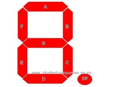 It is not different from an LED in terms of interfacing, by turning the appropriate segments ON and OFF we can display easily the numbers 0 to 9 and optionally the decimal point (DP).
The segments of the displays are normally referred to by letters ‘a’ to ‘g’.
Figures 2 and 3 show how a 7-segment display can display digits.
In figure 2, all the segments (LEDs) are switched on to display the digit “8” with the decimal point. On the other hand, in figure 3, segments a, b, c, d and g are switched on to display the digit “3”. any combination can be used to display any desired digit.
The segments can also be used to display some letters, but this is limited. For example, the letter “b” can be displayed by switching on the segments c, d, e and f and the letter “F” by switching on segments a, e, f and g.
In figure 4, the anode pins of all the segments are connected together and this pin is usually connected to the power supply. Individual segments are turned ON by grounding the required segment pin through the microcontroller by sending a “0” to the pin output.
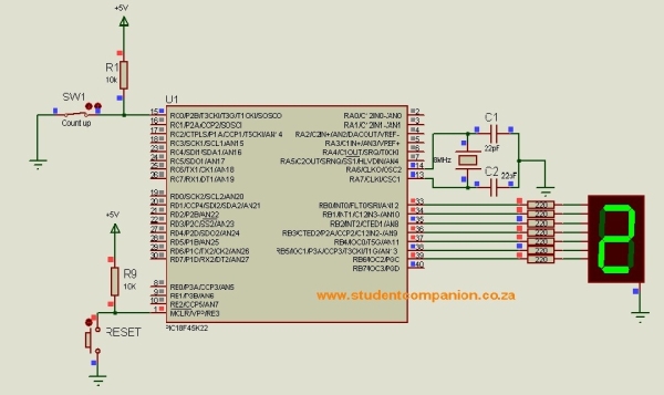
In figure 5 as well as in figure 1, all the cathodes of all the segments are connected together and this pin is usually connected to ground. Individual segments are turned ON by applying voltage to the required segment pin through the microcontroller by sending a “1” to the pin output.
A PIC can source or sink 25mA of current per Input/Output pin. When designing an LED circuit, we have to know the typical voltage drop as we have learnt from the Blinking an LED Connected to a PIC microcontroller article.
As with standard LEDs, it is required to use current limiting resistors in each segment of the display to limit the current as shown in figure 1.
 The easiest way to display a number on the 7-segment is to find a way to determine or look up the pattern corresponding to the digit to be displayed . This can be something like a table showing the numbers and the corresponding segment that should be turned ON or OFF to display something and the required number (this can be in decimal, hexadecimal or in binary format) to be sent to the port where the display is connected to in order to display a specific number.
For more detail: Interfacing 7-Segment Display With PIC Microcontroller – MikroC
- How many segments does a 7-segment display have?
Seven segments plus an optional decimal point, often counted as eight segments. - How are the segments labeled?
The segments are normally referred to by letters a to g. - How do you display the digit 8?
Switch on all segments (a to g) and the decimal point if required. - How do you display the digit 3?
Switch on segments a, b, c, d and g. - How do you display letters like b or F on a 7-segment?
The letter b uses segments c, d, e and f; the letter F uses segments a, e, f and g. - What is the difference between common-anode and common-cathode displays?
In common-anode the anode pins are tied and the segments are turned on by grounding segment pins; in common-cathode the cathode pins are tied and segments are turned on by applying voltage to segment pins. - Do you need resistors for each segment?
Yes, current-limiting resistors are required for each segment. - How much current can a PIC I/O pin source or sink for driving segments?
A PIC can source or sink 25 mA per input/output pin. - What is an easy way to determine which segments to turn on for a given digit?
Use a lookup table or pattern that maps digits to the segments that should be turned on and the port values to send.
