Summary of DAC Sine Wave Generation using TMS320F28027PT with Proteus Simulation
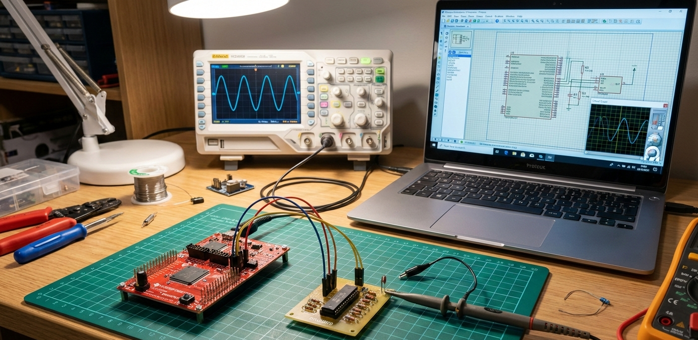
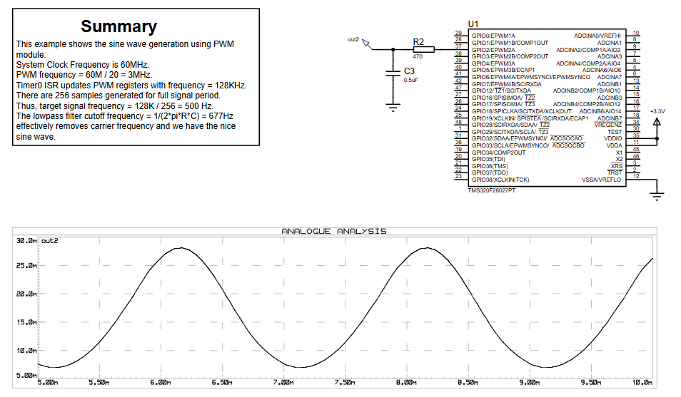
This project implements a PWM-based DAC on a TMS320F28027PT (PICCOLO) microcontroller to generate a clean sine wave. A 256-point lookup table is used with CPU Timer0 interrupts to update PWM duty cycles; the PWM output is low-pass RC filtered (470 Ω, 0.5 µF) and verified in Proteus VSM. The design supports sine, square, and DC outputs and demonstrates firmware, timer-driven updates, and filtering to produce analog signals without a native DAC.
Parts used in the DAC Sine Wave Generation using TMS320F28027PT with Proteus Simulation:
- TMS320F28027PT microcontroller (PICCOLO family)
- ePWM module (on-chip peripheral)
- CPU Timer0 (on-chip timer)
- RC low-pass filter: 470 Ω resistor
- RC low-pass filter: 0.5 µF capacitor
- 3.3V supply
- Proteus VSM simulation environment
- How is the DAC implemented on the PICCOLO microcontroller?
By using the PWM module as a DAC: Timer0 interrupts update PWM duty cycle values from a 256-point sine lookup table. - Why is a low-pass filter required?
To remove the high-frequency PWM carrier and reconstruct the analog sine wave. - Why are 256 samples used for the sine wave?
They provide a smooth waveform while keeping memory usage low. - Can the waveform frequency be changed?
Yes, by modifying the timer interrupt rate or lookup table stepping. - Does this approach work on other PICCOLO devices?
Yes, it is applicable to similar PICCOLO controllers that have PWM modules. - Why use CPU Timer0 for updates?
CPU Timer0 provides precise and consistent timing for waveform generation. - Can square or DC output be generated?
Yes, the code supports square and constant voltage modes selectable at compile time. - What causes waveform distortion in simulation?
Incorrect RC values or a mismatched PWM frequency can affect output quality.