Summary of HUMANOID robotic ARM using pic microcontroller
This tutorial shows how to control a 3D-printed robotic arm using a PIC16F877A microcontroller and potentiometers, generating PWM on GPIO pins via timer interrupts to drive five servos despite the PIC having only two hardware PWM pins. The design uses separate 5V rails for the PIC and servos, reads potentiometer values via AN0–AN4, displays duty cycles on a 16x2 LCD, and connects servos to RD2–RD6. PWM timing matches hobby servos (50 Hz, 0–2 ms pulse), mapping potentiometer readings to duty cycle and toggling GPIOs within a 20 ms cycle.
Parts used in the HUMANOID robotic ARM using pic microcontroller:
- PIC16F877A microcontroller
- 5V voltage regulator 7805 (for PIC, LCD, potentiometers)
- 5V voltage regulator 7805 (for servo motors) labeled +5V(2)
- 12V DC adapter
- Five potentiometers
- Five hobby servo motors
- 16x2 LCD display
- ICSP programmer header (H1) for pickit3
- PCB or breadboard with GPIO/analog extensions
- Wiring and connectors
- 3D-printed robotic arm mechanical parts (or cardboard alternative)
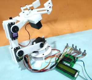
From the assembly line of automobile manufacturing industries to the telesurgery robots in space, Robotic Arms are to be found everywhere. The mechanisms of these robots are similar to a human which can be programmed for similar function and increased capabilities. They can be used to perform repeated actions faster and accurate than humans or can be used in harsh environments without risking human life. We have already built a Record and Play Robotic Arm using Arduino which could be trained to do a particular task and made to repeat forever.
In this tutorial, we will use the industry standard PIC16F877A 8-bit Microcontroller to control the same robotic arm with potentiometers. The challenge with this project is that PIC16F877A has only two PWN capable pins, but we need to control about 5 servo motors for our robot which requires 5 individual PWM pins. So we have to utilize the GPIO pins and generate PWM signals on PIC GPIO pins using the timer interrupts. Now, of course, we could upgrade to a better microcontroller or use a de-multiplexer IC to make things a lot easier here. But still, it is worth giving this project a try for the learning experience.
The mechanical structure of the robotic arm that I am using in this project was completely 3D printed for my previous project; you can find the complete design files and assembling procedure here. Alternatively, if you do not have a 3D printer you can also build a simple Robotic Arm using cardboards as show in the link. Assuming that you have somehow got hold of your robotic Arm lets proceed into the project.
Step 1: Circuit Diagram
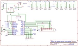
The Complete circuit diagram for this PIC Microcontroller based Robotic Arm is shown below. The schematics was drawn using EasyEDA.
The circuit diagram is pretty simple; the complete project is powered by the 12V adapter. This 12V is then converted to +5V using two 7805 Voltage regulators. One is labeled as +5V and the other is labeled as +5V(2). The reason for having two regulators is that when the servo rotates it pulls in a lot of current which creates a voltage drop. This voltage drop forces the PIC to restart itself, hence we cannot operate both the PIC and the servo motors on the same +5V rail. So the one labeled as +5V is used to power the PIC Microcontroller, LCD and Potentiometers and a separate regulator output which is labeled as +5V(2) is used to power the servo motors.
The five output pins of the potentiometers which provide a variable voltage from 0V to 5V are connected to the analog pins An0 to AN4 of the PIC. Since we are planning to use timers to generate PWM the servo motors can be connected to any GPIO pin. I have selected pins form RD2 to RD6 for the servo motors, but it can be any GPIO of your choice.
Since the program involves a lot of debugging, a 16×2 LCD display is also interfaced to portB of the PIC. This will display the duty cycle of the servo motors that are being controlled. Apart from this I have also extended connections for all GPIO and analog pins, just in case if any sensors need to be interfaced in future. Finally I have also connected the programmer pin H1 to directly program the PIC with pickit3 using the ICSP programming option.
Step 2: Generating PWM Signals on GPIO Pin for Servo Motor Control
Once the circuit is ready we have to figure out how to generate PWN signals on the GPIO pin of PIC to control the servo motor. We have already tired something similar using the Timer interrupt method and were successful. Here we are just going to build on top of it.
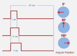
All hobby servo motors work with a frequency of 50Hz. Meaning one complete pulse cycle for a servo motor will be 1/50 (F=1/T) which is 20ms. Of this complete 20ms the control signal is only from 0 to 2ms while the rest of the signal is always off. The below figure shows how the ON time varies only from 0 to 2ms to rotate the motor from 0 degree to 180 degree of the total 20ms duration.
With this in mind we have to write the program in such a way that the PIC reads in 0 to1204 from the potentiometer and maps it to 0 to 100 which will be the duty cycle of the servo motor. Using this duty cycle we can calculate the ON time of the servo motor. Then we can initialize the timer interrupt to overflow at a regular interval such that it acts similar to the millis() function in Arduino. With that, we can toggle the status GPIO pin to be high for a desired duration and turn it off after 20ms (one complete cycle) and then repeat the same process. Now, that we have understood the logic let us get into the program.
Source: HUMANOID robotic ARM using pic microcontroller
- How many servos does the project control?
The project controls five servo motors. - Can the PIC16F877A generate PWM for five servos?
Yes, by generating PWM on GPIO pins using timer interrupts since the PIC has only two hardware PWM pins. - What frequency must the servo PWM use?
Hobby servo motors use 50 Hz, which is a 20 ms cycle. - How is the power supplied to the PIC and servos?
A 12V adapter powers the system; two 7805 regulators provide separate +5V rails for the PIC and for the servos. - Which analog pins read the potentiometers?
The potentiometers are connected to analog pins AN0 to AN4 of the PIC. - Which GPIO pins are used for servo outputs in the example?
The example uses RD2 to RD6 for the servo motors, though any GPIOs can be used. - Why are two 7805 regulators used?
To prevent servo current draw from causing voltage drops that would reset the PIC by isolating servo power from the PIC power. - How are potentiometer readings mapped to servo pulse width?
Potentiometer values (0 to 1024) are mapped to 0 to 100 duty cycle, which is used to compute the ON time within the 20 ms servo cycle. - Is an LCD included and what does it display?
Yes, a 16x2 LCD is interfaced to port B to display servo duty cycle values for debugging. - Can the mechanical arm be built without a 3D printer?
Yes, an alternative cardboard robotic arm design is suggested if a 3D printer is not available.