Summary of How to work with inbuilt Analog Comparators of PIC18F4550- (Part 12/25)
This article details the configuration and application of the two in-built analog comparators within the PIC18F4550 microcontroller. It explains the CMCON register settings for eight operational modes, specifically demonstrating how to use the "Two Common Reference Comparators with Outputs" mode to design proximity sensors using IR LEDs. The guide covers pin multiplexing on Port A, input/output configuration, and provides source code for implementation.
Parts used in the Proximity Sensor Project:
- IR sensor
- PIC18F4550 microcontroller
- Infrared LED
- LED
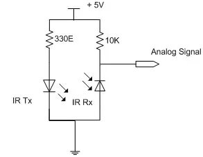
Analog comparators, including inbuilt Analog Comparators, are electronic devices which compare the two voltage signals and provide TTL logic output to indicate the larger signal. The analog comparator is used in various applications where two input signals need to be compared. IR sensor is a very common example where analog comparator is used.
PIC18F4550 consists of two analog comparators and these comparators can be used in eight different modes. The analog comparators’ I/O pins are multiplexed with PortA pins (RA0 – RA5) pins of the controller. The register CMCON is configured to set the mode of the comparator in a PIC microcontroller. The bits of CMCON register are explained below.
|
Bit 7
|
Bit 6
|
Bit 5
|
Bit 4
|
Bit 3
|
Bit 2
|
Bit 1
|
Bit 0
|
|
C2OUT
|
C1OUT
|
C2INV
|
C1INV
|
CIS
|
CM2
|
CM1
|
CM0
|
|
CM2:CM0
|
Mode
|
Description
|
|
000
|
Comparators Reset
|
The comparators remain reset and the output is read as zero
|
|
001
|
One Independent Comparator with Output
|
Comparator 1 is active with external output at RA4/C1OUT pin
|
|
010
|
Two Independent Comparators
|
Both comparators work separately with output changes at C1OUT and C2OUT bits respectively
|
|
011
|
Two Independent Comparators with Outputs
|
Both comparators work separately with external outputs at RA4/C1OUT and RA5/C2OUT pins respectively
|
|
100
|
Two Common Reference Comparators
|
The comparators works separately having common reference voltage on positive reference pins of the comparators with output changes at C1OUT and C2OUT bits respectively
|
|
101
|
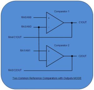
Two Common Reference Comparators with Outputs
|
The comparators work separately having common reference voltage on positive reference pins of the comparators with external outputs at RA4/C1OUT and RA5/C2OUT pins respectively
|
|
110
|
Four Inputs Multiplexed to Two Comparators
|
Both comparators have multiplexed input at negative reference pin of the comparator. The common reference voltage at positive reference voltage pin comes from internal voltage reference module with output changes at C1OUT and C2OUT bits respectively
|
|
111
|
Comparators Off
|
Both comparators remain off
|
Project Source Code
###
// Program to use inbuilt analog comparator of PIC18F4550
void main()
{
TRISA.RA0=1; // Configure as input pin for negative input of Comparator 1
TRISA.RA1=1; // Configure as input pin for negative input of Comparator 2
TRISA.RA2=1; // Configure as input pin for positive input of Comparator 1
TRISA.RA3=1; // Configure as input pin for positive input of Comparator 2
TRISA.RA4=0; // Configure as output pin for output of Comparator 1
TRISA.RA5=0; // Configure as output pin for output of Comparator 2
CMCON=0x05; // ‘Two Common Reference Comparators with Outputs’ Mode
while(1);
}
###
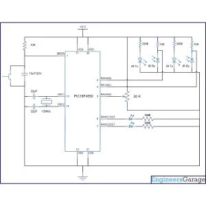
Circuit Diagrams
Project Components
Project Video
Source: How to work with inbuilt Analog Comparators of PIC18F4550- (Part 12/25)
- How many in-built comparators does the PIC18F4550 have?
The PIC18F4550 consists of two analog comparators. - Can the PIC18F4550 comparators replace external ICs like LM324?
Yes, using these in-built comparators saves the cost and connections for providing an extra IC like LM324 or LM339. - Which register is used to set the mode of the comparator?
The CMCON (Comparator Control Register) is configured to set the mode of the comparator. - What mode is selected to design the IR proximity sensors in this project?
The Two Common Reference Comparators with Outputs mode (CM2:CM0 = 101) is selected. - Which pins serve as the output pins for the comparators in the circuit?
The outputs are obtained at RA4/C1OUT and RA5/C2OUT pins. - How can the output bit of Comparator 1 be inverted?
The C1INV bit is used to invert the output bit of Comparator 1. - What happens when CM2:CM0 bits are set to 111?
Both comparators remain off. - Which pins are configured as inputs for the negative reference in Mode 110?
C1 VIN- connects to RA0/AN0 and C2 VIN- connects to RA1/AN1 when CIS is 0.