Summary of How to Simulate PIC Microcontroller in Proteus Design Suite 8
This tutorial explains how to simulate a PIC16F877A microcontroller using Proteus Design Suite v8. It covers Proteus VSM features, benefits of simulation, preparatory knowledge, and a step-by-step guide: creating a new project, drawing the schematic, adding components, placing ground, tying MCLR high with a DC source, setting the PIC clock frequency, loading the compiled .HEX file, and running the simulation to test an LED blinking program.
Parts used in the PIC16F877A LED Blinking Project:
- PIC16F877A microcontroller
- LED
- Current limiting resistor (for LED)
- Ground terminal
- DC voltage source (for MCLR and Vcc)
- Crystal oscillator or clock source (set via PIC properties)
- Proteus Design Suite v8 software (Proteus VSM) <li.Compiled .HEX file (LED blinking program)
- Component library items from Proteus (generic components)
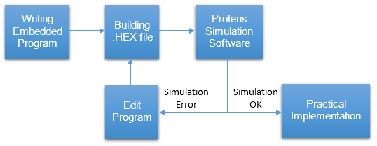
This is our PIC Microcontroller tutorial series. We have already discussed basic beginners guide to PIC. Now let’s see how to simulate the PIC microcontroller?PIC simulation is the important step that you should do before practical implementation of any microcontroller projects.
As Circuits Gallery covers topic of Microcontrollers especially with PIC (Peripheral Interface Controller), this guide shows how to simulate PIC in one of the best PIC microcontroller simulation software ‘Proteus Design Suite Version 8’.
A simulation software can interact with the embedded project with screen indicators for example LED, LCD displays, switches and buttons. The simulation takes place in real time.
 Why we Need Simulation?
What is the purpose of simulation? Before going to the practical implementation of the circuit we have to test whether the embedded program will work perfectly for our project.
Here comes the importance of simulation softwares. Such software provides an environment to test our microcontroller program.
It is possible to play with your microcontroller just as in real world.
This article dealing with the most powerful simulation software the Proteus Design Suite Version 8.
It is good to have the following knowledge before going to PIC Simulation
- Getting Started with PIC Microcontroller
- How to program PIC Microcontroller
- PIC microcontroller Basic connection circuit
What is Proteus VSM?
Proteus Virtual System Modelling (VSM) has mixed mode SPICE circuit simulation, animated components and microprocessor models to ease co-simulation of complete microcontroller based designs.
Over ten years later, Proteus VSM is still primary in the arena with more microcontroller variants and peripherals than any competing product, better debugging tools and instruments and a consistent focus on innovation.
With Proteus you can
- Alter your ‘hardware’ by rewiring the circuit diagram, varying component values for resistors, capacitors etc.
- Removing or making new components to the design.
- You can change your firmware in the IDE of your choice and, once compiled, test the new code on the new system at the press of a button.
- Reprogramming microcontroller: In practical there is limitation to flash the memory of microcontroller but in Proteus you can burn program unlimited times.
- Attain confident that your program will work for real world applications.
This brings you total freedom to experiment with diverse ideas and to discover the optimal design solution for our project. The schematic serves as a ‘virtual prototpye‘ for the firmware and it’s quick and easy to make changes to either.
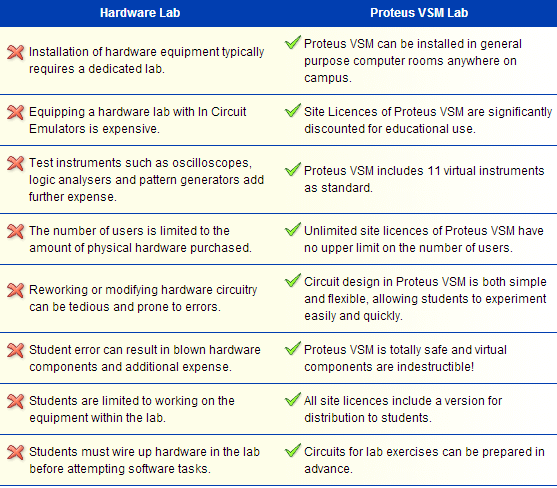
Advantages of Simulation
Let’s start Proteus Simulation
In this example I already build .HEX file of LED blinking program.
Read our old article if you don’t know how to build .Hex file.
Now I’m gonna to show you how to simulate PIC16F877A microcontroller using Proteus.
Step 1: Create a new project
Click New Project button.
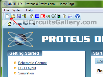
Now give a Name to our project
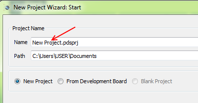
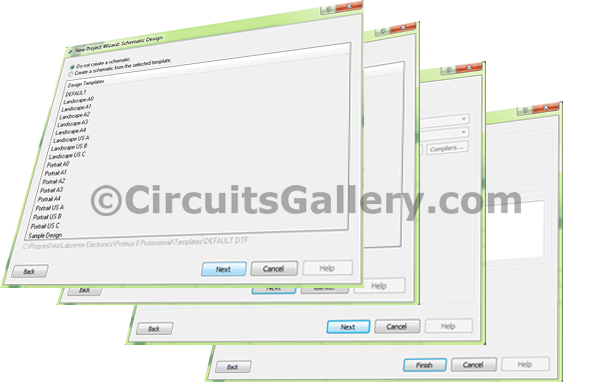
Do not change anything, just follow the default options and click Next until you see Finish button.
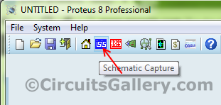
Step 2: Draw the circuit diagram
Now click Schematic Capture button, you will be directed to schematic panel.
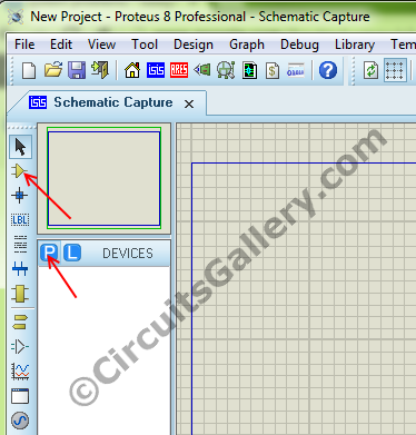
Step 3: Add components to work space
Click P button followed by Component button under Devices for picking components
Step 4:
Choose your component by simply typing the name at Keyword box. After selecting item click OK.
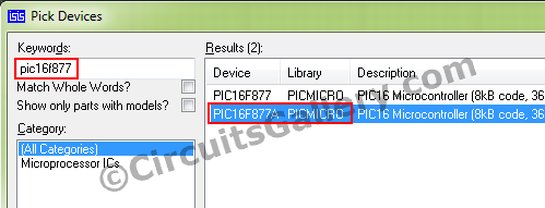
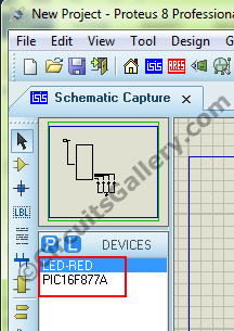
The selected components will listed under Devices.
Step 5:
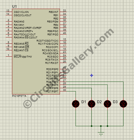
Now draw the circuit diagram as shown below.
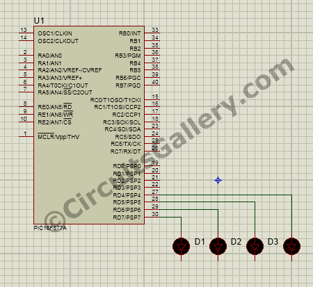
Step 6:
Where is the ground terminal in Proteus 8? Click Terminal mode button to get different terminals,
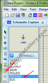
Click Ground and add to our schematic.
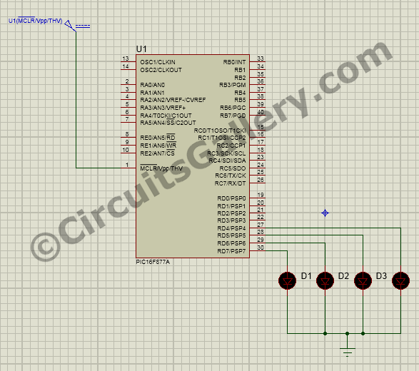
Step 7: Set Memory clear pin to high
Apply MCRL signal to PIC MCU, Click Generator mode button and choose DC.
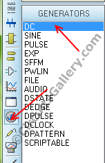
Connect it as shown below diagram.
Double click on the DC terminal and set its voltage as 5.
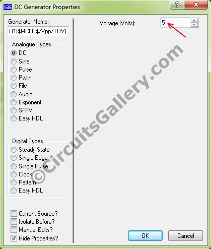
That’s all our basic connection for the simulation over.
Step 8: Set clock frequency to PIC MCU in Proteus
Double click on the PIC IC, the Edit component wizard will open. Set the frequency as same that you did for generating .HEX file. (I compiled my embedded program with 10MHz, hence I selected 10MHz here).
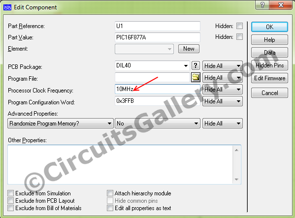
Keep rest options as default.
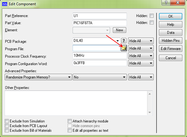
Step 9: Load .HEX file to the schematic diagram of PIC
After setting frequency click browse button to load the .HEX file.
Choose your .HEX file
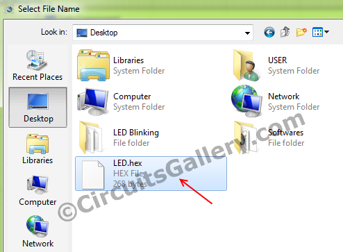
Finally click OK. Now everything ready to go.
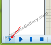
Step 9: Let’s run simulation…!
Click the Run Simulation button at bottom left corner and observe your PIC simulation.
Source : How to Simulate PIC Microcontroller in Proteus Design Suite 8
- Why should I simulate a PIC microcontroller before practical implementation?
Simulation tests whether the embedded program will work correctly before building the real circuit, letting you experiment and debug safely. - What software is used in this tutorial to simulate PIC microcontrollers?
Proteus Design Suite Version 8 with Proteus Virtual System Modelling (VSM) is used. - What prior knowledge is recommended before simulating in Proteus?
Getting started with PIC microcontroller, how to program PIC microcontroller, and PIC basic connection circuit knowledge are recommended. - How do I start a new Proteus simulation project?
Click New Project, give a name, accept default options by clicking Next until Finish, then open Schematic Capture. - How do I add components to the Proteus schematic?
Click the P button, then Component, type the component name in the Keyword box, select it and click OK to add to the Devices list and schematic. - Where is the ground terminal in Proteus and how do I add it?
Click Terminal mode to access different terminals, choose Ground and add it to the schematic. - How do I set the MCLR (memory clear) pin high in Proteus?
In Generator mode choose DC, place it, connect to MCLR, double click the DC terminal and set its voltage to 5V. - How do I set the PIC clock frequency in Proteus?
Double click the PIC IC to open Edit component wizard and set the frequency equal to the frequency used when compiling the .HEX file (example 10MHz). - How do I load my compiled .HEX file into the PIC in Proteus?
Double click the PIC, click browse in the Edit component wizard, choose your .HEX file and click OK. - How do I run the simulation in Proteus?
Click the Run Simulation button at the bottom left corner and observe the simulation in real time.